Transformers play a crucial role in electrical systems, efficiently adjusting voltage levels for safe appliance usage and minimizing grid losses. They operate by converting high transmission voltages to lower, more usable levels without altering power frequency or quantity, thanks to a magnetic circuit. Three-phase transformers are particularly valued for their efficiency in AC power transmission and distribution, offering an economical solution for widespread electrical distribution.
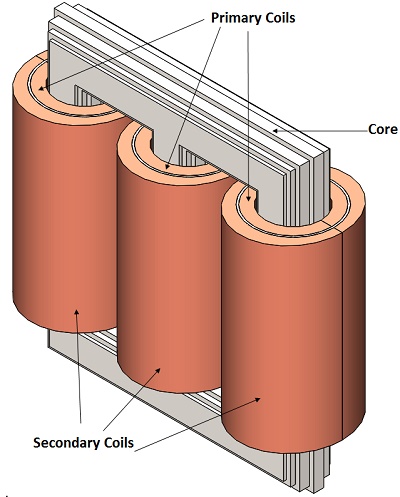
The CAD model for a three-phase cylindrical transformer is intricately designed, featuring a core, along with three primary and secondary coils, illustrating its comprehensive structure aimed at optimizing electrical transformation and distribution efficiency.
To determine the core loss of a three-phase cylindrical transformer, an open circuit test is performed. This involves using an AC Magnetic study combined with thermal analysis to simulate and analyze the transformer's performance under no-load conditions, providing insights into heat generation and magnetic efficiency within the core structure.
In EMS, following an electromagnetic analysis, thermal analysis is seamlessly initiated to evaluate the temperature distribution caused by conduction in solids, utilizing pre-computed heat sources from the electromagnetic study. This process illustrates the integration of AC Magnetic study with Steady State Thermal analysis, providing a comprehensive understanding of thermal behavior in response to electromagnetic phenomena.
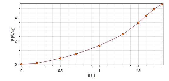
The simulation model includes a laminated steel core, three primary and secondary coils, and air, with each material's properties detailed in a specified table. Additionally, the core loss curve for M36 material is depicted, providing essential data for analyzing the transformer's efficiency under operational conditions.
| Component | Material | Relative permeability | Electrical Conductivity (S/m) | Thermal Conductivity (W*m-1 * k-1) |
| Core | laminated steel (M36 at 0.36mm; Mass density: 7700 kg/m^3) | 1616 | 2.32558 e+006 | 43 |
| Primary Coils/Secondary Coils | Copper | 0.99991 | 5.7e+007 | 401 |
| Coils Air, Inner Air, Outer Air | Air | 1 | 0 | 0.024 |
To simulate an open circuit operation in a three-phase transformer, the primary windings are energized with the rated voltage while the secondary windings remain open, simulating a no-load condition. In this model, the secondary coils are represented as solid entities with zero net RMS current. The primary coils, on the other hand, are modeled to carry 250 A-turns (50 turns at 5A), with a phase difference of 120 time-degrees between them. Both primary and secondary coils utilize 19 AWG wire for consistency in the simulation parameters.
In EMS simulations, convection is modeled as the process through which heat transfers from a solid surface to an adjacent fluid or gas in motion. This is achieved by assigning a convection boundary condition to all components designated as Air, facilitating the accurate calculation of heat dissipation in the surrounding air.
In the AC Magnetic study conducted by EMS, a wide array of parameters including inductance, resistance, impedance, and more are evaluated. Specifically, the simulation quantifies various losses within the transformer's core, such as eddy loss, hysteresis loss, excess loss, and overall core loss, during an open circuit simulation. These detailed findings are visually presented and explained in Figure 3, offering a comprehensive view of the transformer's electromagnetic and thermal performance under simulated conditions.

Figure 3 - Results table in EMS
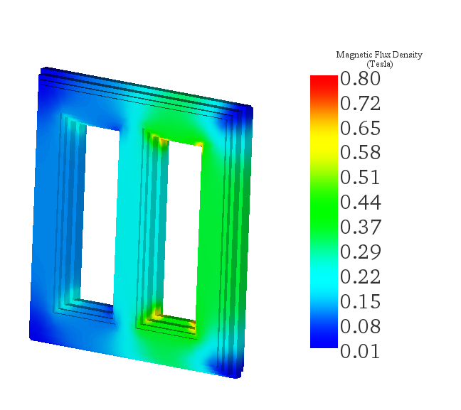
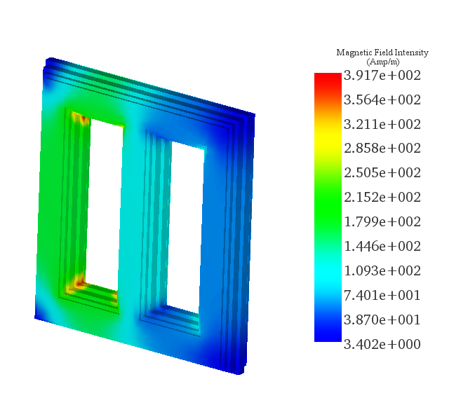
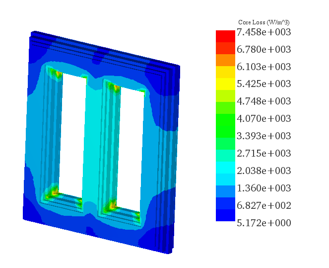
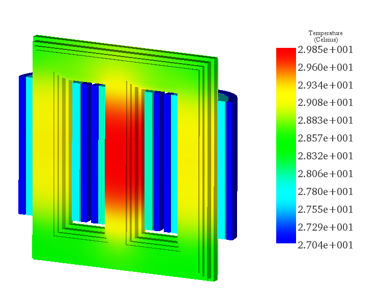
EMS generates comprehensive 3D plots to visually represent various aspects of the transformer's performance in an open circuit simulation. These include the Magnetic Flux Density, Magnetic Field Intensity, Core Loss, and Temperature Distribution within the transformer. Each of these critical parameters is depicted in Figures 4 through 7, respectively, offering valuable insights into the electromagnetic and thermal behavior of the transformer under simulated no-load conditions.
The 3-phase Cylindrical Transformer application note highlights the significance of transformers in electrical systems for voltage adjustment and grid loss reduction. It emphasizes the efficiency of three-phase transformers in AC power distribution, providing an economical solution for widespread electrical transmission. Through intricate CAD modeling and open circuit simulations, the note elucidates the transformer's core loss determination and its thermal behavior under no-load conditions. The integration of AC Magnetic and thermal analysis in EMS offers a comprehensive understanding of electromagnetic and thermal phenomena within the transformer. Material properties, coil definitions, and thermal inputs are meticulously detailed, contributing to accurate simulations. The results, presented visually through 3D plots and tables, provide valuable insights into the transformer's electromagnetic and thermal performance. Overall, the note underscores the importance of transformer analysis in optimizing electrical distribution efficiency.
| Share on |