

Electronic Design Automation (EDA) Electromagnetic Simulation
Simulate chip–package–board systems to predict impedance, delay, crosstalk, losses and EMI in high-speed electronics.
High-speed electronics depend on controlled impedance, low crosstalk and stable power delivery across chip, package and PCB. EMWorks models traces, vias, packages, connectors and planes in 3D, computing fields, S-parameters, delay, eye-diagram metrics and losses so you can debug signal and power integrity issues and tune layouts before fabrication.
-
Chip Package Board systems
Use EMWorks to simulate chip-package-board systems on full 3D geometry. Analyze signal integrity, power integrity, crosstalk, and return paths so you can optimize high-speed channels and PDNs before fabrication. -
.webp)
Printed Circuit Boards (PCBs)
Use EMWorks to simulate real PCB layouts, including traces, vias, planes and components. Evaluate signal and power integrity, EMI, and heating so you can fix issues and optimize stackups before fabrication. -
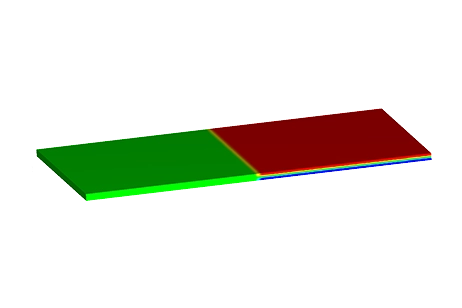
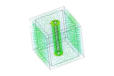
Capacitors
Use EMWorks to model capacitors of any shape—parallel plate, coaxial, busbar, and custom 3D structures. Extract capacitance, visualize electric fields, evaluate parasitics, and estimate breakdown limits before building hardware.