A BLDC motor
This application note showcases EMWorks2D's capability in simulating a BLDC motor with MotorWizard, emphasizing the practicality of 2D FEM analysis in electric motor design. It outlines the advantages of 2D simulation in balancing computational efficiency with accuracy, suitable for rapid, early-stage development of innovative electric motors, despite the deeper insights provided by more resource-intensive 3D simulations.
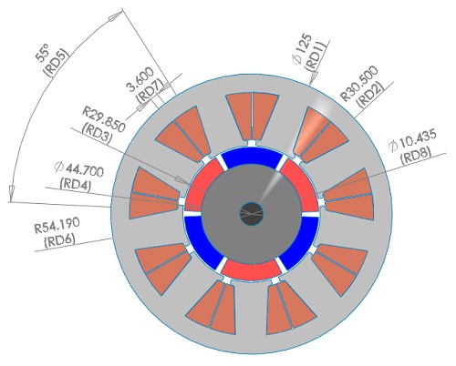
Figure 1 contains the 2D geometry of the simulated BLDC motor. It consists of a 3-phase machine with 12 slots and 6 poles. Hence, the symmetry angle of this motor is $$ \Theta = \frac{2\pi}{3} $$ mechanical degrees. The stator and rotor cores are made of steel ( $$ \mu_r = 1000 $$ ). The rotor poles, having surface surface-mounted structure, are made of ferrite permanent magnets ( $$ B_r = 0.4\,T $$ ). The shaft has non-magnetic material.
The double-layer windings are arranged on 3 phases with a coil pitch equal to 1. Each phase has 1456 turns.
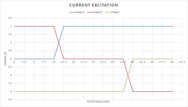
The excitation of each phase involves three ideal square-wave currents in a wye-connected three-phase winding. At any moment, two phases are active, and one is idle, with phase activation cycling based on the rotor's position, repeating every 360 electrical degrees of rotation.
In this simulation, where Eddy effects and iron losses are omitted, a static magnetic analysis is conducted. A parametric sweep study is implemented to evaluate the output torque and magnetic flux, alongside inductance and flux linkage outcomes. These torque results will be benchmarked against those reported in reference [3].
Meshing
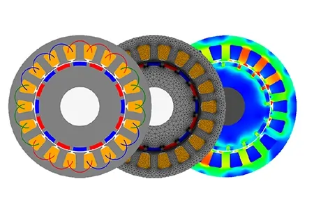
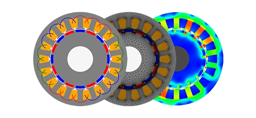
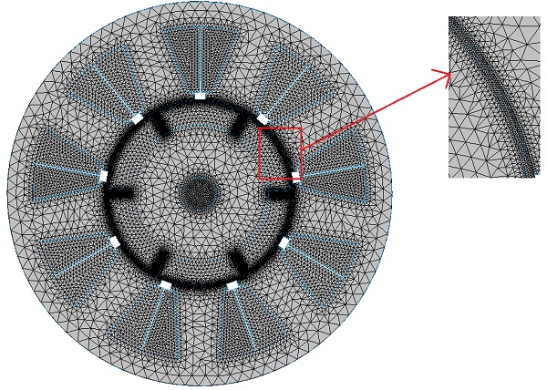
The meshing process is a critical aspect of FEM simulations. Using smaller element sizes, or a higher number of mesh elements, can improve result accuracy but may also increase computation time. EMWorks2D offers a flexible and user-friendly mesher that supports mesh control on specific surfaces and edges that are sensitive to mesh quality. Figure 3 illustrates the meshed model with mesh control applied to the air gap, demonstrating the software's capability to balance detail and computational efficiency.
Results and Discussion
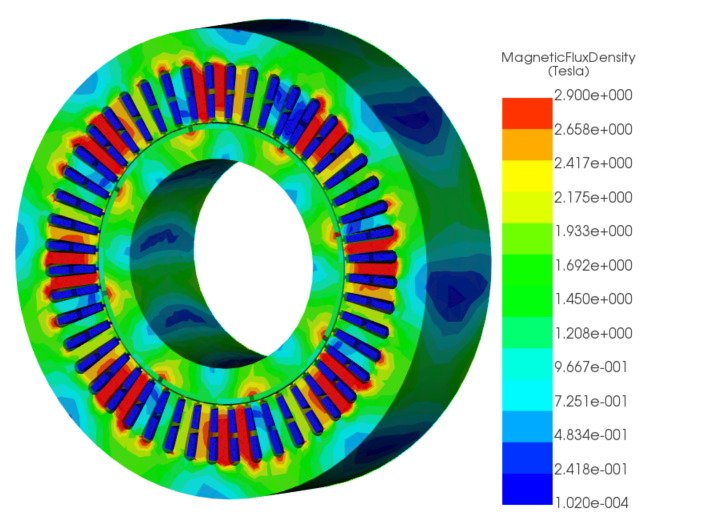
The simulation was executed at various rotor positions, producing corresponding results. Figure 4a) displays the magnetic flux density in fringe plot form, and Figure 4b) shows vector plots within the machine at the initial position (0 degrees, with coil A not excited). The magnetic flux density moves from and to the machine's center, attributed to the opposite polarity of the excited phases B and C. Notably, high magnetic flux density is observed at the stator teeth corners, highlighting areas of intense magnetic activity.
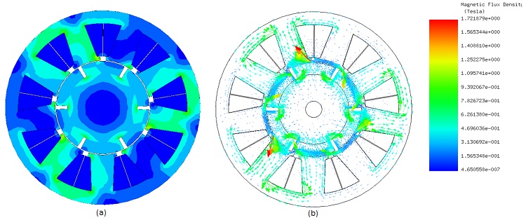
Figure 5 presents an animation plot depicting the magnetic flux lines as a function of rotor angle, visually demonstrating how the flux lines change with the rotor's movement. Meanwhile, Figure 6 features contour lines of the magnetic vector potential, indicating that the majority of the magnetic field is confined within the motor. This visualization helps in understanding the distribution and behavior of the magnetic field as the rotor rotates, highlighting the efficiency of magnetic confinement in the motor's design.
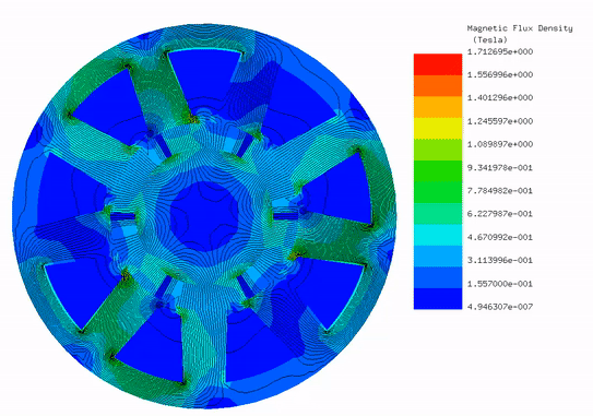
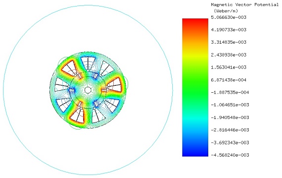
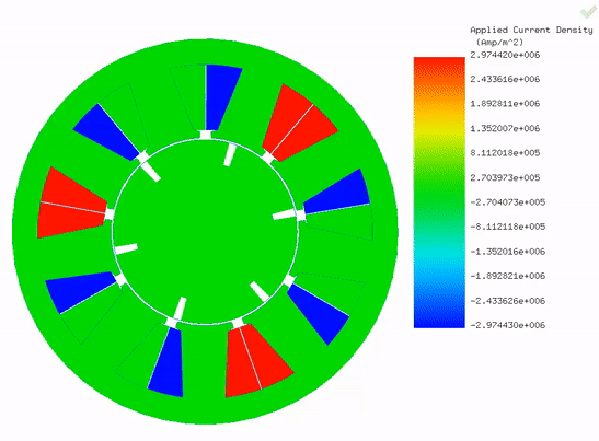
Figure 7 showcases an animation of the applied current density across various rotor positions, effectively illustrating the excitation of the three phases as the rotor turns. This dynamic commutation is critical for achieving the highest possible torque while minimizing torque ripple, ensuring smooth and efficient motor operation.
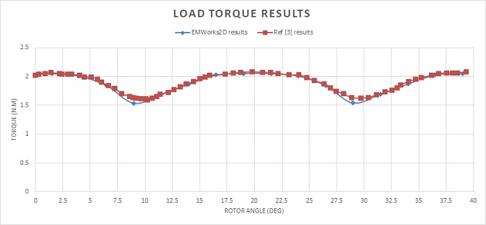
The figure illustrates load torque results calculated by EMWorks2D across an angular range from $$ 0^\circ $$ to $$ \frac{\theta}{3} = 40^\circ $$ comparing these findings with those reported in reference [3]. The torque curve is marked by a low ripple amplitude yet features a high number of ripples, totaling 18 within one full revolution. The maximum and minimum computed torque values are 2.05 Nm and 1.53 Nm, respectively, with an average developed torque of approximately 1.89 Nm.
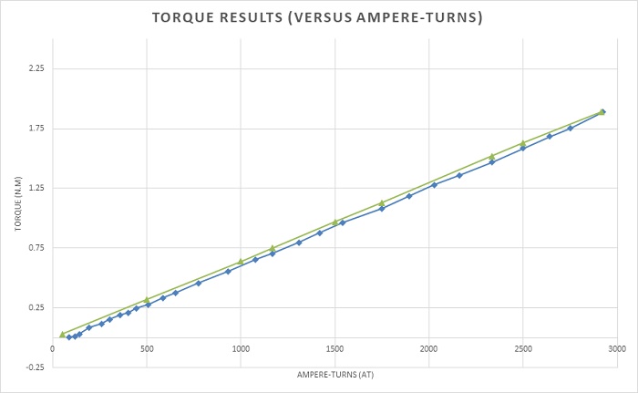
Figure 9 demonstrates that the torque of the BLDC motor increases linearly with ampere-turns, starting from a cogging torque of 0.1 Nm to an average of 1.89 Nm at 2916 A-t. This showcases a key advantage of brushed DC motors—linear torque response—without the need for brushes or commutators, now inherent to BLDC motors.
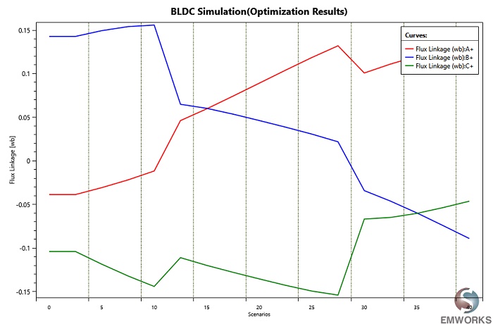
Table 1 details uniform inductance values across all motor phases, while Figure 10 plots the flux linkage results for the three-phase windings, illustrating the motor's electromagnetic behavior.
| Phase A, B, and C | |
| Self-inductance (H) | 0.64085 |
| Mutual inductance (H) | 0.61795 |
Conclusion
This application note explores the simulation of a Brushless DC (BLDC) motor using EMWorks2D and MotorWizard, highlighting the effectiveness of 2D Finite Element Method (FEM) analysis in electric motor design. The study emphasizes the advantages of 2D simulation for balancing computational efficiency with accuracy, particularly beneficial for rapid, early-stage motor development. It presents a 3-phase BLDC motor model with 12 slots and 6 poles, utilizing a static magnetic analysis to evaluate output torque, magnetic flux, inductance, and flux linkage. The simulation demonstrates the motor's performance at various rotor positions, showing how magnetic flux density and eddy currents vary with rotor angle, underscoring the motor's efficient magnetic confinement and dynamic commutation for optimized torque production. The results reveal a torque curve with low ripple amplitude, a linear increase in torque with ampere-turns, and consistent inductance values across phases, confirming the model's accuracy and potential for reducing torque ripple and enhancing motor efficiency. This application note validates the utility of 2D FEM analysis in the preliminary design phase of electric motors, offering insights into magnetic behavior and torque generation with less computational demand than 3D simulations.
References
[1]: G. M’boungui, E. K. Appiah, A. A. Jimoh, T. R. Ayodele. Simple Numerical Two-Dimensional Magnetostatic Analysis of a Fractional Slot Winding Brushless DC Motor. Proceedings of the World Congress on Engineering and Computer Science 2013 Vol I
WCECS 2013, 23-25 October, 2013, San Francisco, USA