Physics
Capacitance is a fundamental concept in physics, defined as the ratio of the amount of charge stored in a capacitor to the potential difference between its electrodes. Let's consider an example of a parallel-plate capacitor, as shown in Figure 1. In this example, the capacitor is constructed by filling the space between two square plates with blocks of three different dielectric materials.
The capacitance of each dielectric block is determined by the equations (1), (2), and (3):
$$ C_1 = \frac{K_1 \epsilon_0 A_2}{d} $$ (eq.1)
$$ C_2 = \frac{K_2 \epsilon_0 \frac{A}{2}}{\frac{d}{2}} $$ (eq.2)
$$ C_3 = \frac{K_3 \epsilon_0 \frac{A}{2}}{\frac{d}{2}} $$ (eq.3)
$$ C = C_1 + \left( \frac{1}{C_2} + \frac{1}{C_3} \right)^{-1} = C_1 + \frac{C_2 C_3}{C_2 + C_3} = \frac{K_1 \epsilon_0 A}{2d} + \frac{\epsilon_0 A}{d} \left( \frac{K_2 K_3}{K_2 + K_3} \right) = \frac{\epsilon_0 A}{d} \left( \frac{K_1}{2} + \frac{K_2 K_3}{K_2 + K_3} \right) $$ (4)
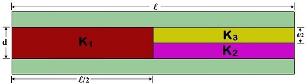
Figure1 - parallel plate capacitor with three dielectrics
With the following parameters:
$$ d = 2 \, \text{mm}, \quad l = 100 \, \text{mm} $$
$$ A = 100 \, \text{mm} \times 50 \, \text{mm} = 5000 \, \text{mm}^2 $$
$$ K_1 = 1.93, \quad K_2 = 3.25, \quad K_3 = 4 $$
The equivalent capacitance is: $$ C = 6.1050 \times 10^{-11} \, \text{F} $$
Model
The following instructions show how to prescribe material to individual parts of your model and compute capacitance between two elements.
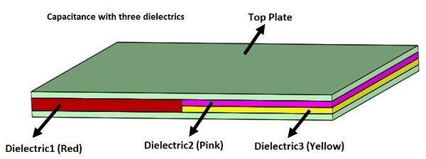
A model of the capacitor with multiple dielectrics has been created in Solidworks. The space between the parallel plates is filled by 3 different dielectric materials. The plate surface is $$ 50 \times 100 \, \text{mm}^2 $$, while the thickness of each plate is 1mm. The thickness of the dielectric block $$ K_1 $$ is the same as the distance between the plates: 2mm; the thickness of the blocks $$ K_2 $$ and $$ K_3 $$ is half of that:1mm (Figure 2).
The simulation is performed in the EMS Electrostatic study ![]() . Aluminum is used as a material for the electrode plates, Teflon, polyimide, and nylon are used for dielectric $$ K_1 $$,$$ K_2 $$and $$ K_3 $$ , respectively. All these materials with their electromagnetic properties can be found in the EMS material library.
. Aluminum is used as a material for the electrode plates, Teflon, polyimide, and nylon are used for dielectric $$ K_1 $$,$$ K_2 $$and $$ K_3 $$ , respectively. All these materials with their electromagnetic properties can be found in the EMS material library.
Assign material
Under Materials in the EMS manager tree, right-click on Dielectric 1.
Select Apply Material

The Material Browser folder appears
Under “Cables” folder, choose Teflon
Click Apply and Close

Compute capacitance
To obtain capacitance results from EMS:
In the EMS manger tree, Right-click on the Electrostatic study
 folder.
Select Properties

Under General Properties, check Compute Capacitance box
Click OK
 .
.
Boundary Conditions
To account for the capacitance, a Floating conductor boundary condition is assigned to both plates.
To do so:
In the EMS manager tree, Right-click on the Load/Restraint
 folder.
Select Floating Conductor
 .
.Click inside the BodiesSelection
 box and then select the Topplate.
Click OK
 .
.
For the bottom plate:
In the EMS manger tree, Right-click on the Load/Restraint
 folder.
Select Floating Conductor
 .
.Click inside the BodiesSelection
 box and then select the Bottom plate.
Click OK
 .
.
Results
In the EMS manager tree, under Results ![]() , open the Results Table to find the Capacitance matrix. EMS solution for total capacitance is $$ 6.1056 \times 10^{-11} $$ F (Figure 3) and it matches the theoretical result very closely.
, open the Results Table to find the Capacitance matrix. EMS solution for total capacitance is $$ 6.1056 \times 10^{-11} $$ F (Figure 3) and it matches the theoretical result very closely.
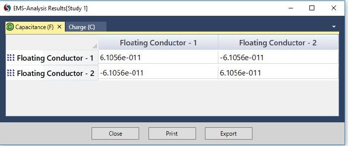
Figure 3 - EMS results for Capacitance