A MEMS Microsensing Membrane
Electrostatic actuation, common in MEMS, relies on electrostatic fields to induce forces on structures like RF micro-switches and pressure sensors. EMS Simulation software from EMWorks is utilized to study membrane deflection under DC voltage, neglecting gravity's influence.
CAD Model
Figures 1 and 2 illustrate the geometry of the model under analysis. It comprises two 40 ?m square membranes, with one fixed at the bottom and a movable one at the top, controlled by two serpentine springs. The device's thickness along the z-axis is 1 ?m.
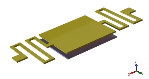
Figure 1 - The geometry of the analyzed model
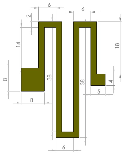
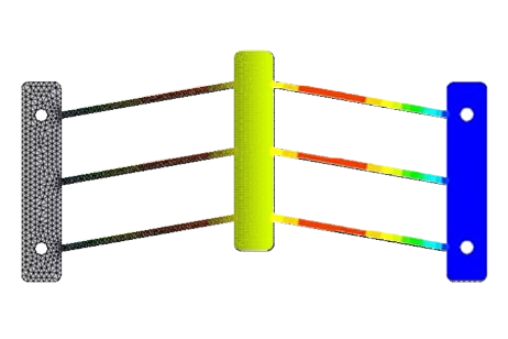
Figure 2 - The geometry of the serpentine spring
All the units are given in micrometers.
Simulation Setup
The Electrostatic module of EMS, coupled with structural analysis, computes and visualizes both the electric results and the mechanical deformation of the moving membrane.
To conduct an analysis using EMS, the following crucial steps have been undertaken:
1. Selecting appropriate materials for all solid bodies.
2. Defining necessary electromagnetic inputs.
3. Applying structural boundary conditions.
4. Meshing the entire model and executing the solver.
Materials Properties
Table 1 below summarizes the essential material properties required for the simulation.
Table 1 - Properties of materials assigned to the model
| Material Name | Relative permittivity | Density (kg/$$ m^3 $$) | Elastic Modulus (Pa) | Poisson’s Ratio |
| Platinum | 1 | 2145 | 170e+09 | 0.26 |
| Air | 1 | 0 | Not required | Not required |
Boundary conditions
Electrical boundary condition
1. Fixed voltage 1(0V)
The top membrane is grounded, as depicted in Figure 3. Arrows indicate the symbols of the boundary conditions assigned to it.
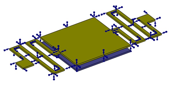
Figure 3 - Fixed voltage applied to the top membrane
2. Fixed voltage 2 ( positive voltage)
The fixed electrode is assigned a positive voltage. Figure 4 illustrates the location where the voltage is applied.
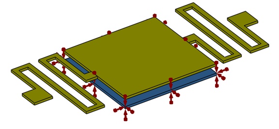
Figure 4 - Fixed voltage applied to the bottom membrane
Structural boundary condition
Fixed boundary conditions are applied to the bottom membrane and to the anchors of the two serpentine springs, as depicted in Figure 5.
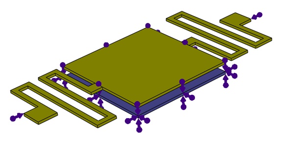
Figure 5 - Fixed constraint applied on the bottom membrane
Meshing
The model geometry does not feature overly complex shapes. Mesh control has been applied to all solid bodies of the model, ensuring sufficient accuracy for both electrical and structural results. Figure 6 displays the generated mesh.
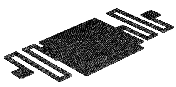
Figure 6 - The meshed model
Simulation Results
Various voltages have been applied to the bottom membrane, generating electrostatic forces responsible for the deflection of the top membrane. Figure 7 illustrates the resultant displacement as a function of the applied voltage computed by EMS, compared with the reference results.
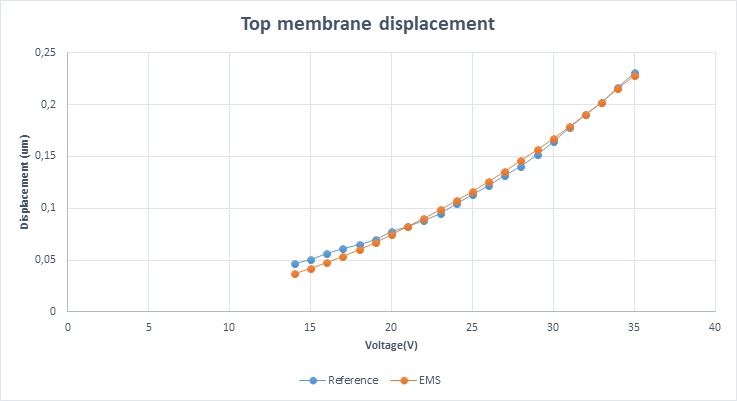
Figure 7 - displacement as a function of voltage for EMS and reference
Visualization of the Results for 33v applied Voltage:
EMS provides the capability to determine the resultant electric rigid body force acting on structural components. In our scenario, we seek to identify the electric force acting on the top membrane. Table 2 displays the components of the electric force vector exerted on the membrane, measured in Newtons.
Electric Force (Results Table)

The Analytical formula
C: the capacitance
V: the voltage applied to the bottom membrane
Correlation between EMS and the reference results:
Table 3 - Comparison between EMS and the reference results
| EMS Result | Reference Result | |
| Resultant Displacement under 33V (in μm) | 0.202591 | 0.201708 |
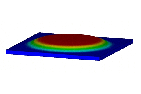
Resultant Displacement plot:
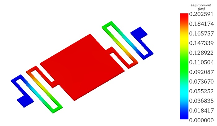
Figure 8 shows that the maximum displacement occurs at the square membrane
Conclusion
This application note explores the behavior of a microelectromechanical system (MEMS) microsensing membrane under electrostatic actuation, a common phenomenon in MEMS devices. Utilizing EMS Simulation software from EMWorks, the study focuses on membrane deflection induced by DC voltage, with gravity's influence neglected. The CAD model depicts two 40 µm square membranes—one fixed at the bottom and another movable one at the top—controlled by serpentine springs. EMS, coupled with structural analysis, enables computation and visualization of both electric and mechanical responses. Material properties, boundary conditions, and meshing strategies are meticulously defined to ensure accurate simulation results. Various voltages applied to the bottom membrane generate electrostatic forces, causing deflection in the top membrane. EMS results, including displacement and electric force vectors, are compared with reference data, showcasing good agreement. The study provides valuable insights into the behavior of MEMS microsensing membranes under electrostatic actuation, contributing to the understanding and optimization of MEMS device design and performance.
References
[1]: https://www.emworks.com/
[2]: P. A. Manoharan and D. Nedumaran, 2010, “Modeling-Simulation and Analysis of MEMS Capacitive Millibar Pressure Sensor,” J. Nanotechnol. Eng. Med 1(4)