A Comb-Drive Actuator
Electrostatic comb-drive actuators, known for easy design and application in fields like optical and wireless communication, biomedical engineering, and nanotechnology, aim to improve travel distance and force output. These devices consist of interdigitated fingers—one set fixed and the other movable, driven by electrostatic force under applied voltage. The EMS electro-structural module calculates this movement, focusing solely on the electrostatic forces, with gravity effects disregarded.
CAD Model
Figure 1 displays the geometry of the analyzed model, which has a thickness of 2 micrometers along the z-axis. All dimensions are provided in micrometers.
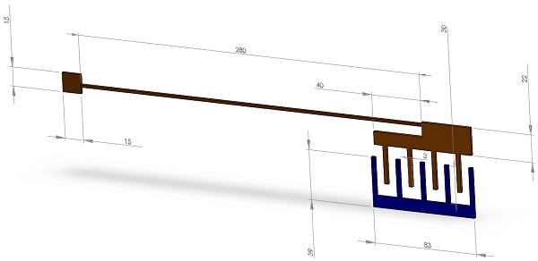
Figure 1 - The geometry of the analyzed actuator
Materials properties
Table 1 given below summarizes the material properties required for the simulation.
| Material Name | Relative permittivity | Electrical conductivity (Mho/m) | Elastic modulus (N/m2) | Poisson’s Ratio |
| PolySilicon | 4.5 | Not required | 160e+09 | 0.22 |
| Air | 1 | 0 | Not required | Not required |
Table 1 - Properties of materials assigned to the model
Boundary conditions
Electrical boundary condition
Fixed voltage 1(0V)
In Figure 2, the finger colored blue is grounded, with arrows indicating the boundary conditions applied to it.
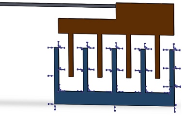
Figure 2 - Fixed voltage applied on the upper finger
Fixed voltage 2 (30V)
The movable part of the actuator is assigned a positive voltage, as illustrated in Figure 3, indicating the application points for the voltage.
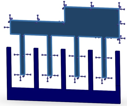
Figure 3 - Fixed voltage applied on the lower finger
Structural boundary condition
Fixed boundary condition
Meshing
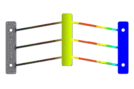
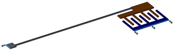
The model geometry is relatively simple, and applying mesh control to refine the lower finger is adequate for precise electrical and structural outcomes. As shown in Figure 4, the mesh on the movable part is finer than on other parts, while the beam connecting the lower finger to its anchor doesn't require such fine meshing.
The upper finger, depicted in blue in Figure 5, has a coarser mesh since it won't undergo any deflection.
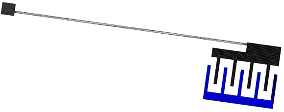
Figure 5 - The meshed model
Simulation Results
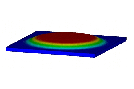
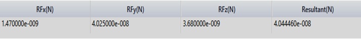
After completing the simulation, EMS generates a table detailing the resultant electric rigid body force on the model's components. Specifically, the focus is on identifying the electric force acting on the lower finger—the movable part of the actuator. Figure 6 displays the components of the electric force vector acting on the plate, with the force values provided in Newtons.
Electric force (Results table)

The Analytical formula
C: the capacitance of the actuator
V: the voltage applied to the moving finger
n: the number of moving fingers
t: The thickness of the actuator
g: the gap between the upper and lower fingers
$$ \epsilon_0 $$: absolute electrical permittivity
Correlation between EMS and the reference result $$ A_{\phantom{0}} $$
| EMS Result | Simulation Result | |
| Resultant Displacement under 30V (in meters) | 4.16e-08 | 5e-08 |
Reaction force (Spring restoring force)
Resultant Displacement plot
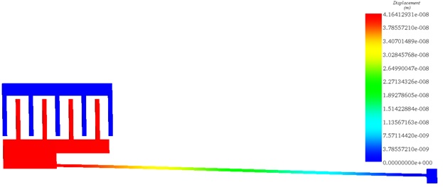
Figure 6 - The deformed geometry of the actuator
Conclusion
The application note delves into the optimization of electrostatic comb-drive actuators, focusing on enhancing travel distance and force output. Utilizing the EMS electro-structural module, the study calculates the movement generated by electrostatic forces, omitting gravity's influence for simplicity. The analyzed model, with a focus on the geometry and material properties essential for the simulation, provides a detailed insight into the design and operational mechanics of these actuators.
Key to this investigation is the application of specific electrical boundary conditions to simulate the electrostatic forces acting between the interdigitated fingers of the actuator. By assigning different voltages to the movable and fixed parts, the study meticulously examines the resultant electric force and its impact on the actuator's displacement. The simulation's precision is further enhanced by tailored mesh control, ensuring accurate electrical and structural outcomes.
The findings underscore the actuator's capability to produce significant displacement under a 30V applied voltage, demonstrating the potential of comb-drive actuators in various fields, including optical and wireless communications, biomedical engineering, and nanotechnology. The correlation between EMS results and reference data validates the simulation's accuracy, offering valuable insights for optimizing the performance of MEMS electrostatic comb-drive actuators.
References
[1]: S. Gupta, T Pahwa, R Narwal, B.Prasad and D. Kumar. Optimizing the Performance of MEMS Electrostatic Comb Drive actuator with different Flexure Springs.