A MEMS Thermal Actuator
Micro-electro-mechanical systems (MEMS) enable the miniaturization of complex engineering devices to a micrometer scale, serving diverse applications such as micro-positioning, micro-fixturing, and micromanipulation. Among MEMS devices, micro-thermal actuators play a crucial role by converting thermal energy into force and motion. This study focuses on investigating a low-voltage micro-thermal actuator capable of generating significant thermally-induced deflections.
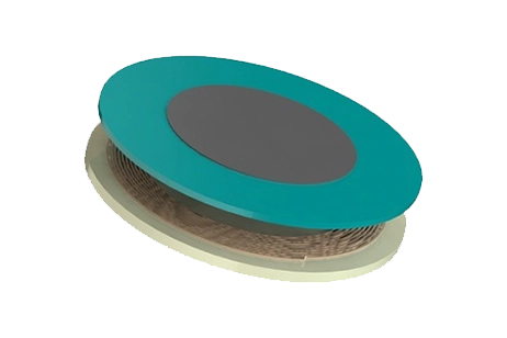
![Electron-microscope-image-of-thermal-actuator-[1]](/ckfinder/userfiles/images/Electron-microscope-image-of-thermal-actuator-%5B1%5D%20%282%29.jpg)
Figure1 - Electron microscope image of the thermal actuator [1]
CAD Model
In this study, we examine a U-shaped actuator comprised of two parallel arms: a cold arm and a hot arm. These arms are connected to the substrate pads on one side and to each other on the other side, as depicted in Figure 2. To analyze the mechanical displacement of this micro-device resulting from temperature expansion effects, we employ EMS simulation coupled with thermo-structural analysis. This integrated approach enables us to accurately calculate the movement and deformation of the actuator under varying thermal conditions, providing valuable insights into its performance and behavior.
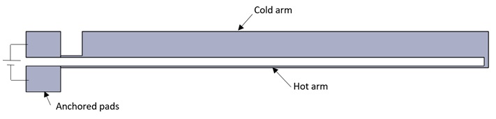
Figure 2 - The basic design of the U-shaped thermal actuator.
Table 1: Model dimensions [2]
| Part | Dimension (µm) |
| Hot arm length | 495 |
| Hot arm width | 2 |
| Cold arm length | 470 |
| Cold arm width | 30 |
| Arms separation | 10 |
| Connecting bar width | 10 |
| Pad length | 40 |
| Pad width | 30 |
Simulation Setup
To compute and visualize the mechanical displacement of the thermal actuator device under study, we utilize the Magnetostatic module alongside steady-state thermal and structural analyses.
The simulation setup comprises the following steps:
1. Selecting an appropriate material.
2. Defining the necessary electromagnetic inputs.
3. Specifying the required thermal inputs.
4. Applying structural boundary conditions.
5. Meshing the entire model and executing the solver.
For our case study, we employ the properties of materials listed in Table 2:
Table 2:Polysilicon material properties
| Property | Electrical conductivity (S/m) |
thermal conductivity (W/m. K) |
Thermal expansion coefficient (/K) |
Elastic Modulus (GPa) |
Poisson’s ratio |
| Polysilicon | 43.5 E+03 | 150 | 2.9 E-06 | 169 | 0.22 |
The microactuator is defined as a solid coil carrying a voltage of 5V, with the hot-arm connected pad serving as the entry port. Both anchored pads initially have a temperature of 0°C. Thermal convection is applied to the ambient air body by setting the initial (ambient) temperature to 273.15 K and the convection coefficient to 10 W/m²K. A "Fixed" constraint structural boundary condition is applied to both sides of the anchored pads, as illustrated in Figure 3:
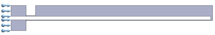
Figure 3 - Applied mechanical boundary conditions.
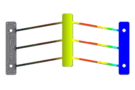
The entire model employs fine mesh control to enhance result accuracy, as depicted in Figure 4.
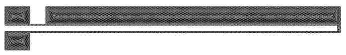
Figure 4 - Meshed model.
Results
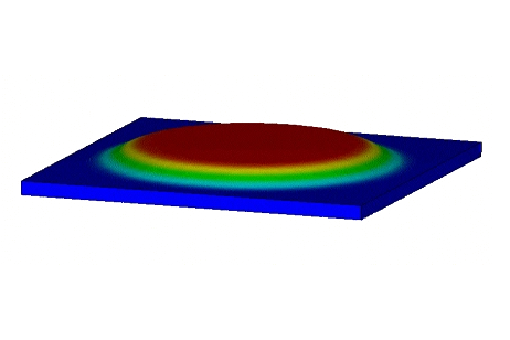
The thermal distribution results are presented in Figure 5. Due to the voltage difference across the pads, a temperature disparity between the two arms occurs, reaching a maximum value of 864°C at the most critical zone of the thin arm.
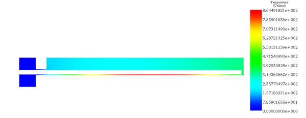
Figure 5 - Temperature distribution across the actuator.
The mechanical displacement resulting from thermal expansion reaches 16.99 µm. Primarily, the actuator moves in the region connecting the two arms.
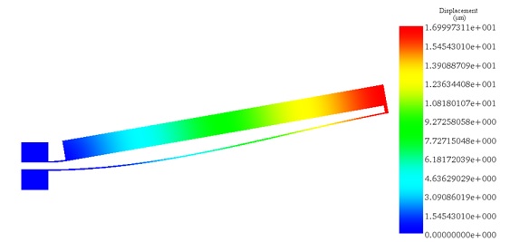
Figure 6 - Resultant displacement plot.
The comparison between EMS andthe reference [2] results for the actuator deflection can be found in Table 3.
Table 3:Comparative table between EMS and the reference [2] results.
| EMS | Reference [2] | |
| Deflection (µm) | 16.99 | 17 |
Conclusion
In conclusion, this study delved into the analysis of a low-voltage micro-thermal actuator within the realm of micro-electro-mechanical systems (MEMS). Through the utilization of EMS simulation coupled with thermo-structural analysis, significant insights were gained into the behavior and performance of the actuator. The investigation focused on understanding the mechanical displacement resulting from temperature expansion effects in the U-shaped actuator design. By employing fine mesh control and considering various material properties, the simulation setup was meticulously crafted to ensure accuracy in the results. The obtained thermal distribution revealed a notable temperature disparity between the two arms, with the thin arm reaching a maximum temperature of 864°C. Additionally, the mechanical displacement resulting from thermal expansion was measured at 16.99 µm, primarily concentrated in the region connecting the two arms. The comparison between EMS and reference results for actuator deflection showcased close alignment, highlighting the reliability and effectiveness of the simulation approach. Overall, this study contributes valuable insights into the design and analysis of micro-thermal actuators, essential components in the field of MEMS.
References
[2]. Hristov, Marin Hristov, et al. "Design and Investigation of a Thermal Actuator." PROCEEDINGS OF THE XVII INTERNATIONAL SCIENTIFIC AND APPLIED SCIENCE CONFERENCE–ELECTRONICS ET 2008. 2008.