MEMS
MEMS devices are classified into electrostatic, electromagnetic, piezoelectric, and electro-thermal types based on their actuation source. Electro-thermal actuation, leveraging thermal expansion from joule heating via current through actuator beams, is utilized in applications like tunable capacitors, optical modulators, RF switches, and micro-manipulators. These actuators offer compactness, stability, and high force at low voltages.
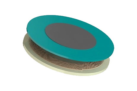
![Electrothermal-actuator [1]](/ckfinder/userfiles/images/Electrothermal-actuator-%5B1%5D%282%29.jpg)
Figure 1 - Electrothermal actuator [1].
CAD Model
A combined magnetostatic and thermo-structural analysis evaluates the V-beam electro-thermal actuator. This actuator comprises a 30×6mm shuttle linked to six beams (26.4mm in length and 1mm in width) and anchored by two 6×30mm supports, with an overall thickness of 1mm along the Z axis.
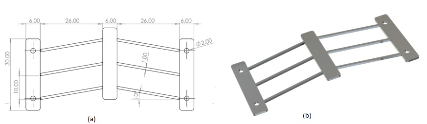
Figure 2 - a) Drawing of the V-beam thermal actuator b) 3D Model of the thermal actuator.
Simulation Setup
Using EMS's Magnetostatic module, combined with steady-state thermal and structural analyses, enables the calculation and visualization of the shuttle's temperature and displacement. The process entails: selecting materials, defining electromagnetic and thermal inputs, setting structural boundaries, meshing, and initiating the solver.
Materials
For our case study, we utilize specific material properties as detailed in Table 1:
Table 1 - Material properties.
| Part | Density (Kg/$$ m^3 $$) | Relative permeability | Electrical conductivity (S/m) | Specific heat capacity (J/kg. K) | Thermal conductivity (W/m. K) | Elastic Modulus (Pa) | Poisson’s ratio | Thermal expansion coefficient (1/K) |
| Aluminum | 2700 | 1 | 3.57 E+07 | 910 | 235 | 71 E+09 | 0.36 | 23.1 E-06 |
| air | 0 | 1 | 0 | 1000 | 0.024 | Not required | ||
Electromagnetic Inputs
The thermal actuator is described as a solid coil that conducts a 40 A DC current.
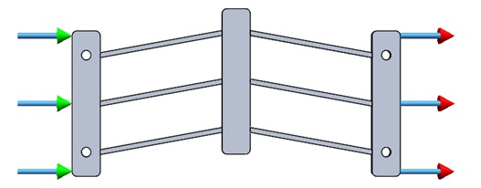
Figure 3 - Applied current input.
Thermal Input
The thermal convection settings for the ambient air in the simulation specify an initial (ambient) temperature of 303.15 K and a convection coefficient of 15 W/m²K for the surrounding air.
Mechanical boundary conditions
Fixed boundary conditions are applied to the thermal actuator's anchors, as illustrated in Figure 4.
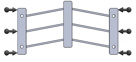
Figure 4 - Applied mechanical boundary conditions.
Meshing
Mesh Control is implemented on the shuttle and the six beams, targeting areas of anticipated maximum temperature and displacement, as depicted in Figure 5.
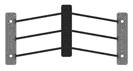
Figure 5 - Mesh of the model.
Results
EMS enables the visualization of results through 3D plots and curves, showcasing parameters such as applied current density, temperature and heat flux distribution, mechanical displacement, stress, and more.
Table 2 presents the DC resistance of the V-beam thermal actuator as determined by EMS simulations alongside an analytical comparison, highlighting the resistance of the thermal actuator against the analytical value for comprehensive analysis.
| EMS | Analytical ( reference) | |
| Electric Resistance ($$ \Omega $$) | 5.59 E-04 | 5.73 E-04 |
$$ R = R_a (1 + K \Delta T) $$ [1]
$$ R_a \left(1 + K \Delta T \right) I^2 = h_c A_c \Delta T $$ [1]
$$ \Delta T = \frac{R_a I^2}{h_c A_c} - K R_a I^2 $$ [1]
I=40 A (current intensity)
Ra =4.96E-04 $$ \Omega $$ (Ambient temperature resistance)
Ac =1553.6 m $$ m^2 $$ (convection area)
hc=15 W/$$ m^2 $$.K(convective heat transfer coefficient)
k=3.9.10-3 1/°C (temperature coefficient)
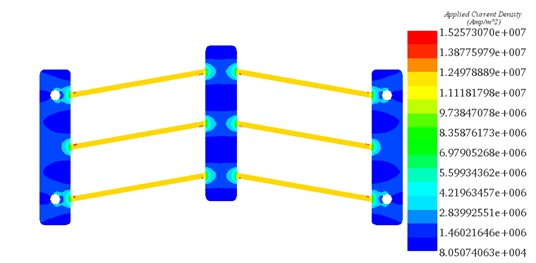
Figure 6 - Plot of the applied current density.
Figure 6 illustrates the distribution of current density within the V-beam thermal actuator, showcasing how the current flows through the device.
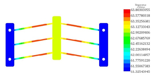
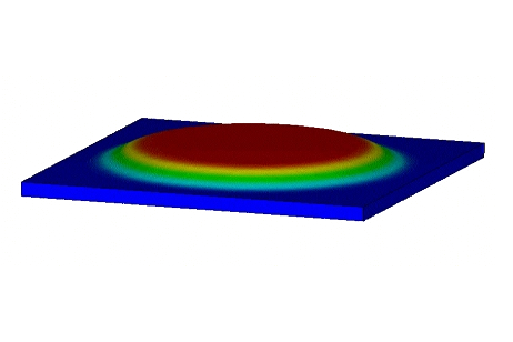
Figure 7 - Plot of temperature distribution.
Figure 7 depicts the temperature distribution within the V-beam thermal actuator, showing a peak temperature of 63.8 °C.
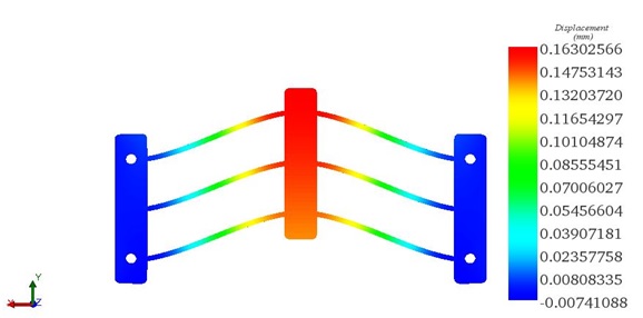
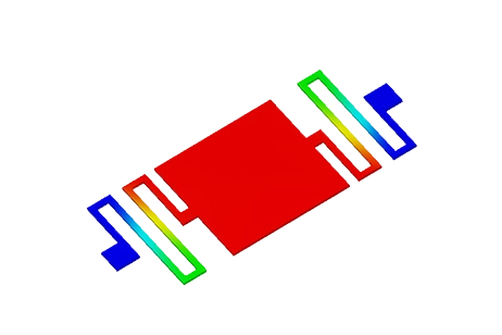
Figure 8 - plot of Y displacement plot .
Figure 8 displays the displacement distribution along the Y axis in the V-beam thermal actuator, reaching a maximum displacement of 0.163 mm. This maximum temperature of 63.8 °C occurs on the beams, attributed to the concentration of current in that area. The shuttle shows the highest mechanical deflection, 0.163 mm, along the Y axis due to this effect. Table 3 compares the temperature and displacement results obtained from EMS simulations with reference values, showcasing the accuracy of EMS in predicting thermal and mechanical behaviors.
Table 3: Comparative table between EMS and the reference [1].
| EMS | Reference [1] | |
| Temperature (°C) | 63.8 | 63.5 |
| Displacement (mm) | 0.163 | 0.165 |
Conclusion
In conclusion, this application note delves into the electro-thermal modeling of MEMS devices, particularly focusing on the V-beam thermal actuator. MEMS devices, categorized into various types based on actuation sources, find applications in fields like tunable capacitors, optical modulators, RF switches, and micro-manipulators. The study utilizes electro-thermal simulations to evaluate the thermal and mechanical behavior of the V-beam actuator. By combining magnetostatic and thermo-structural analyses, the study accurately predicts parameters such as temperature distribution, displacement, and electric resistance. Results showcase the effectiveness of the electro-thermal simulations in capturing the intricate behaviors of the actuator, with temperature peaking at 63.8°C and maximum displacement reaching 0.163 mm along the Y-axis. Comparative analysis with reference data confirms the reliability and accuracy of the simulations. Overall, this study contributes to the understanding of electro-thermal dynamics in MEMS devices, emphasizing the potential for precise control and efficient design of such devices in various applications.
References
[1]. Radu-Stefan Chiorean, “Electro-Thermo-Mechanical Modeling of V-beam Actuator”,8th international conference interdisciplinarity in engineering INTER-ENG 2014,9-10 october 2014, Tirgu-Mures, Romania.