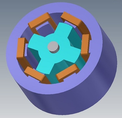
A switched Reluctance Motor
This example illustrates the analysis of a 6/4 switched reluctance motor using EMS within Autodesk Inventor. Table 1 outlines the SRM's dimensions, with both stator and rotor cores made from non-oriented M-19 silicon steel. The 4-phase windings, composed of copper, feature 120 turns per coil. A parametric study was conducted to compute electromagnetic torque, focusing on one stator phase's torque around a rotor pole. The rotor was displaced from 0 to 46 degrees to analyze torque variation.
| Rotor poles number | 4 |
| Stator outer core diameter | 72 mm |
| Rotor outer core diameter | 40.5 mm |
| Air gap length | 0.25 mm |
| Rotor pole arc | 32 deg |
| Stator pole arc | 28 deg |
| Motor length | 36 mm |
| Shaft diameter | 10 mm |
Results
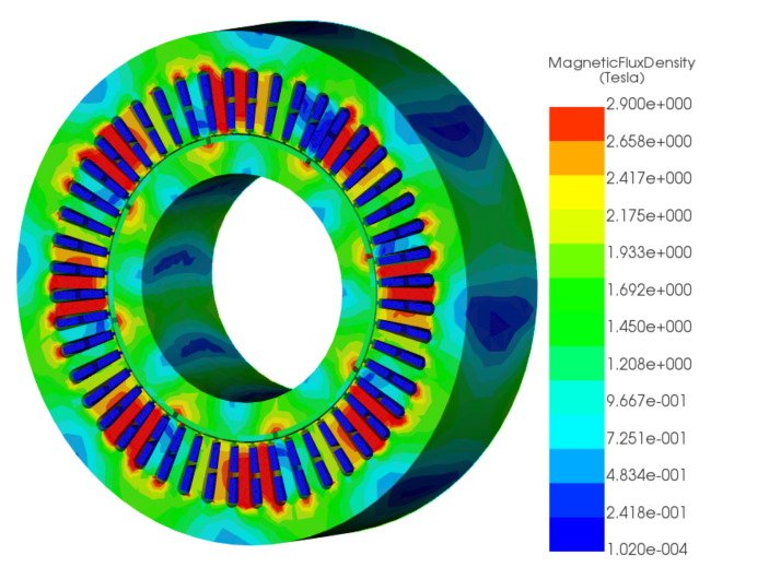
The magnetic fields in both rotor and stator cores at different rotor angles are depicted in the figures below. Fringe and vector plots are utilized to visualize the magnetic flux behavior at varying rotor positions. Figures 2a) and 3a) display the fringe and vector plots, respectively, at the unaligned position (0 deg) of the rotor. This position is characterized by high magnetic reluctance, resulting in nearly zero electromagnetic torque.
At 18 degrees rotor position, shown in Figures 2b) and 3b), the magnetic flux forms closed paths from the rotor to stator poles, leading to the highest torque production. Figures 2c) and 3c) illustrate the fringe and vector plots for the aligned position (46 deg) where magnetic reluctance and torque values are minimal, as stator and rotor poles are in opposite directions.
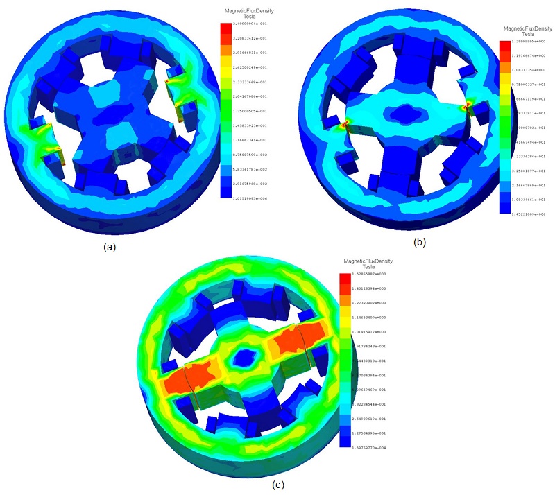
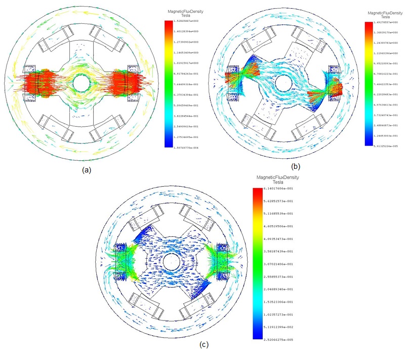
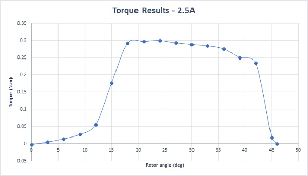
Figure 4 illustrates the torque curve plotted against the rotor angle. It shows that the torque starts from zero at the unaligned position (0 deg), peaks between 18 deg to 40 deg, and returns to zero at the aligned position (46 deg). The maximum torque value, approximately 0.30 Nm, is achieved at 18 deg.
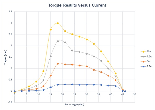
Since the reluctance torque is directly influenced by the winding currents, Figure 5 displays torque plots at different values of winding current.
Conclusion
The application note examines a 6/4 switched reluctance motor (SRM) using EMS within Autodesk Inventor, focusing on electromagnetic torque analysis. Parametric studies investigated torque variations around a rotor pole, observing magnetic flux behavior at different rotor angles. Fringe and vector plots illustrated magnetic field distribution in both rotor and stator cores. At unaligned positions, high magnetic reluctance resulted in minimal torque production, while at 18 degrees, closed magnetic flux paths generated the highest torque. Conversely, at the aligned position (46 deg), minimal reluctance and torque values were observed. The torque curve depicted torque variation with rotor angle, peaking between 18 to 40 degrees. Maximum torque, around 0.30 Nm, was achieved at 18 degrees. Additionally, torque plots at different winding current rates highlighted the direct influence of winding currents on reluctance torque. The study underscores the significance of rotor alignment in maximizing torque output and provides valuable insights into SRM performance, aiding in the optimization of SRM designs for various applications.