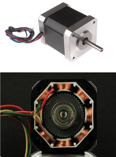
A Stepper Motor
Stepper motors, which are brushless DC motors dividing a full rotation into equal steps, are ideal for precise positioning in devices like 3D printers and CNC machines due to their accuracy in step movements. They offer excellent low-speed torque and speed control, making them suitable for robotics and process automation. However, their efficiency decreases with no load as they draw maximum current, leading to heat generation. Their torque also diminishes at higher speeds, and without integral feedback, they rely on external methods for position confirmation.
The Study
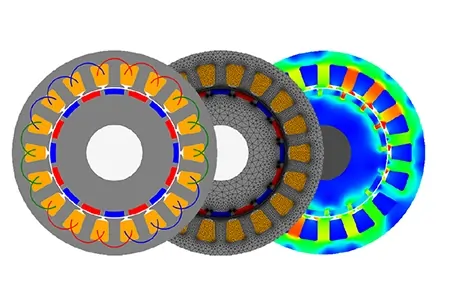
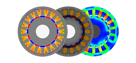
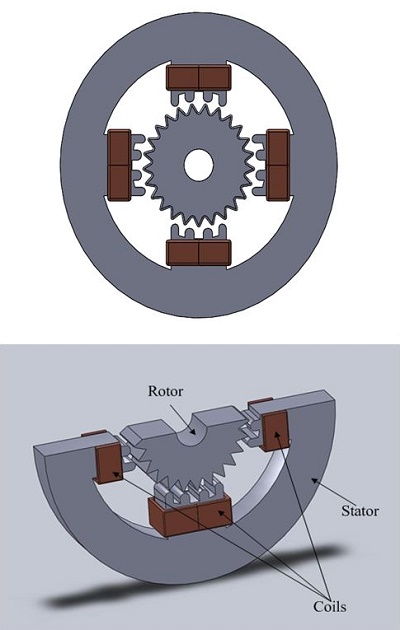
A stepper motor with a cogged rotor is analyzed using EMS's Transient magnetic analysis, focusing on a stator with four spokes wrapped in copper coils. The analysis involves applying a pulsed current to each coil with a time delay, calculating the electromagnetic force and torque on the rotor, and tracking the magnetic flux density through the rotor and stator across all time steps. EMS also provides the current density within the system.
The EMS Transient Magnetic module is designed for analyzing and visualizing time-varying magnetic fields, useful for studying effects like eddy currents, power losses, and magnetic forces. The analysis process, which can be linear or non-linear, involves four key steps: selecting appropriate materials for all components, applying necessary boundary conditions (Loads/Restraints), meshing the model, and finally running the solver to obtain results.
Materials
In EMS's Transient Magnetic analysis, a comprehensive set of material properties is essential for accurate simulation outcomes, as outlined in Table 1. This requirement ensures the precise representation of materials in the analysis, affecting the simulation's overall accuracy and reliability.
| Components / Bodies | Material | Relative permeability | Conductivity (S/m) |
| Rotor | Mild Steel | 2000 | 1.1e+006 |
| Outer Air | Air | 1 | 0 |
| Inner Air | Air | 1 | 0 |
| Coil | Copper | 0.99991 | 57e+006 |
| Stator | Mild Steel | 2000 | 1.1e+006 |
ElectroMagnetic Input
In the study, four coils are employed alongside the rotor to evaluate the virtual work, requiring detailed calculations as outlined in Table 3. This approach aims to precisely assess the electromagnetic interactions and resulting forces within the system, crucial for understanding the motor's performance and optimizing its design.
Table 2 - coils information
| Name | Number of turns |
| Wound Coil (1-4) | 10 |
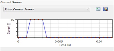
In Transient Magnetic analysis, defining the excitation waveform for the coil, either as a voltage or current source, is crucial. This specification directly influences the simulation's accuracy in depicting electromagnetic behaviors over time.
| Name | Torque Center | Components / Bodies |
| Virtual Work | At origin | Rotor and Permanent Magnets |
Meshing
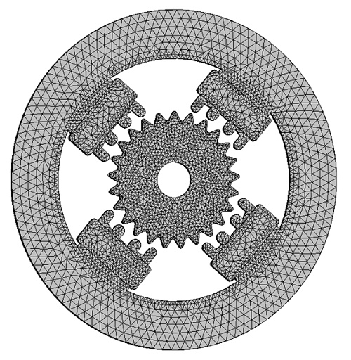
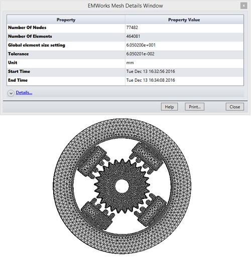
Meshing is crucial in EMS design analysis, determining simulation precision by estimating optimal element sizes based on model geometry. Larger elements offer quicker, approximate results, while smaller elements enhance accuracy. Mesh Control allows for quality adjustments on specific parts, influencing the mesh's detail level as shown in the meshed model example.
Table 4 - Mesh control
| Name | Mesh size | Components /Bodies |
| Mesh control 1 | 4.00 mm | Coils / Rotor/ Stator |
| Mesh control 2 | 1.500 mm | Inner Air |
Results
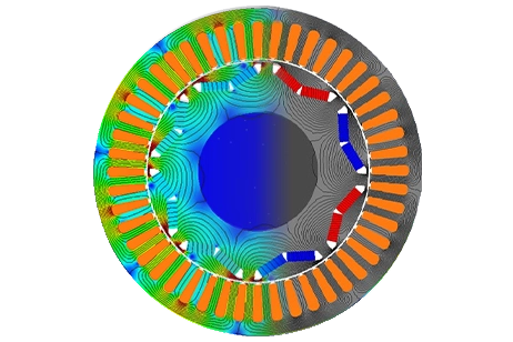
Running the simulation yields extensive results. It provides data on Magnetic Flux Density, Applied Current Density, Force Density, and a detailed results table with model parameters, including force and torque. This comprehensive analysis aids in understanding the electromagnetic behavior of the model under study.
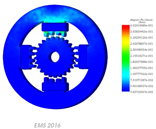
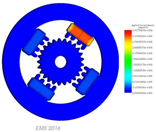
Figure 7 - Applied Current Density at 0.004 s, during every T/4 only one coil is excited
Conclusion
In conclusion, this application note delves into the intricacies of stepper motors, highlighting their significance in precise positioning applications like 3D printers and CNC machines. While stepper motors offer exceptional low-speed torque and speed control, their efficiency diminishes under no-load conditions, leading to heat generation. Additionally, torque decreases at higher speeds, necessitating integral feedback for accurate positioning. The study employs EMS's Transient Magnetic analysis to examine a stepper motor's cogged rotor, providing insights into electromagnetic interactions and torque generation. With detailed material properties and waveform excitation specifications, the analysis ensures accurate simulation outcomes. Meshing plays a crucial role in determining simulation precision, while the comprehensive results offer valuable data on magnetic flux density, current density, and force distribution. Overall, this analysis enhances understanding of stepper motor performance and aids in optimizing their design for various applications.