What is a Brushless DC Motor?
Brushless DC electric motors (BLDC motors, BL motors) (Figure 1), also known as electronically commutated motors (ECMs, EC motors), are synchronous motors powered by a DC electric source via an integrated inverter/switching power supply, producing an AC electric signal for motor operation. Efficiency is a key feature due to the rotor's magnet-bearing design, eliminating the need for commutators and brushes. Sensors and electronics control the inverter output for amplitude, waveform, and frequency regulation, ensuring optimal performance and efficiency.
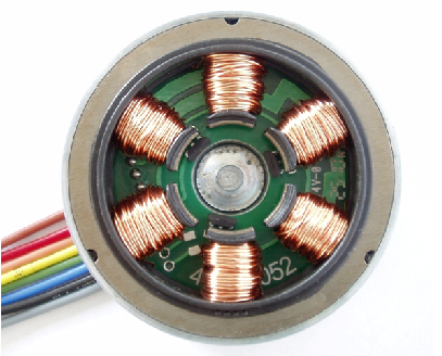
Figure 1 - BLDC motor
Brushless DC motors (BLDC) find extensive applications across diverse industries including industrial control, automotive, aviation, automation systems, healthcare equipment, and more. Specific applications include:
1. Computer hard drives and DVD/CD players
2. Electric vehicles, hybrid vehicles, and electric bicycles
3. Industrial robots, CNC machine tools, and belt-driven systems
4. Washing machines, compressors, and dryers
5. Fans, pumps, and blowers.
CAD Model
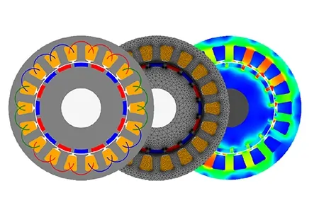
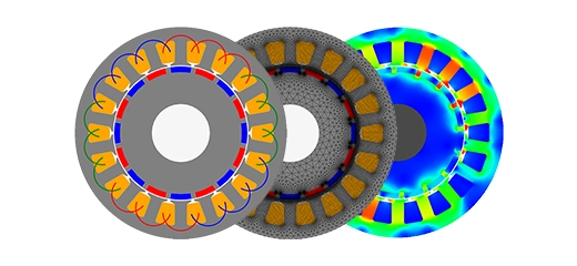
The considered motor features an 8-magnet rotor and a 12-coil stator (Figure 2). Magnetic forces generated by the excitation coils and permanent magnets drive the rotor's rotation. Through EMS, users can conduct multiple studies to modify materials, turn numbers, current flow, and part geometry. EMS enables associating each study with a design table, streamlining parameter optimization for enhanced motor performance.
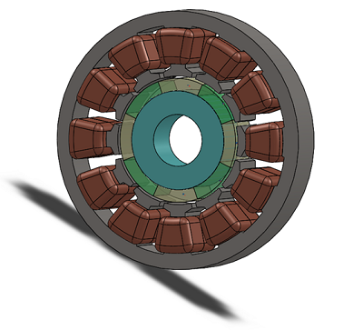
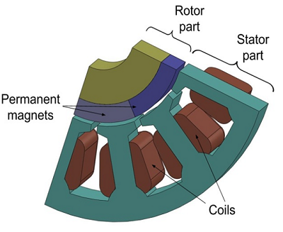
Figure 2 - 3D model of BLDC
The Study
The Magnetostatic module of EMS calculates and visualizes magnetic flux and intensity in the motor, along with coil inductance and electromagnetic force on the rotor. Following the creation of a Magnetostatic study, key steps include material assignment, boundary condition application, meshing, and solver execution. Additionally, coupling Magnetostatic analysis with thermal simulation provides insights into motor thermal behavior.
Materials
In the Magnetostatic analysis conducted with EMS, the essential material properties required are outlined in Table 1. Additionally, Figure 4 depicts the B-H curve of the utilized steel.
| Components / Bodies | Material | Relative permeability | Conductivity (S/m) | Thermal conductivity (W/m*k) |
| Rotor | AISI 1010 Steel | Nonlinear | 6.9e+006 | 65.2 |
| Outer Air | Air | 1 | 0 | 0.024 |
| Inner Air | Air | 1 | 0 | 0.024 |
| Coils | Copper | 0.99991 | 57e+006 | 401 |
| Stator | AISI 1010 Steel | Nonlinear | 6.9e+006 | 65.2 |
| Permanent magnets | S2818 | 1.0388 | 0 | 69 |

Figure 3 - Permanent magnets of the rotor: Coercivity: 819647 A/m, Remanence: 1.07 T
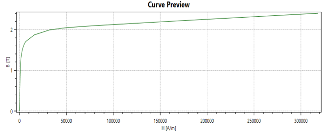
Figure 4 - AISI 1010 Steel BH Curve
ElectroMagnetic Input
In this study, 8 coils (Table 2) are applied, and the rotor (Table 3) is where we need to calculate the virtual work.
| Name | Number of turns | Current excitation |
| Wound Coil (1-8) | 200 | 1 A |
| Name | Torque Center | Components / Bodies |
| Virtual Work | At Origin | Rotor and Permanent Magnets |
Meshing
Meshing is a critical phase in design analysis, where EMS calculates an optimal element size based on factors like volume, surface area, and geometric intricacies. The resulting mesh size (nodes and elements) is influenced by the model's geometry, dimensions, element size, tolerance, and mesh control settings. During initial design stages, a larger element size can expedite solutions, while finer meshes may be necessary for precision. Mesh quality is enhanced through Mesh Control (Table 4), which fine-tunes solid bodies and faces. Figure 6 illustrates the meshed model post-Mesh Controls application.
| Name | Mesh size | Components /Bodies |
| Mesh control 1 | 1.200 mm | Coils |
| Mesh control 2 | 7.000 mm | Rotor |
| Mesh control 3 | 1.000 mm | Magnets |
| Mesh control 4 | 5.000 mm | Stator |
| Mesh control 5 | 0.6699000 mm | Inner air |
Table 4 - Mesh control
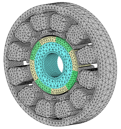
Figure 4 - Meshed model
Results
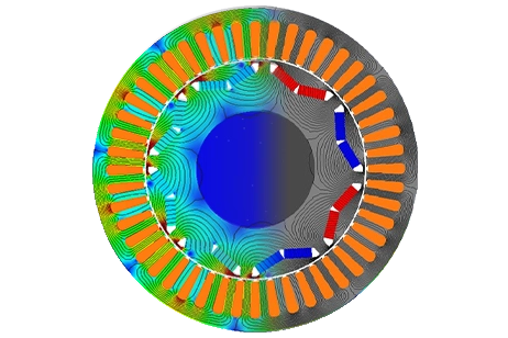
Following simulation completion, the Magnetostatic Module coupled with the thermal solver yields comprehensive results, including Magnetic Flux Density (Figures 5 and 6), Magnetic Field Intensity (Figure 7), Force density (Figure 8), Temperature Distribution (Figure 9), and a results table detailing computed model parameters, force, and torque (Figure 10).
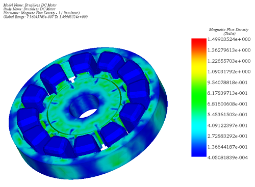
Figure 5 - Magnetic Flux Density, fringe plot
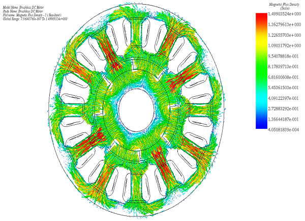
Figure 6 - Magnetic Flux density, vector plot
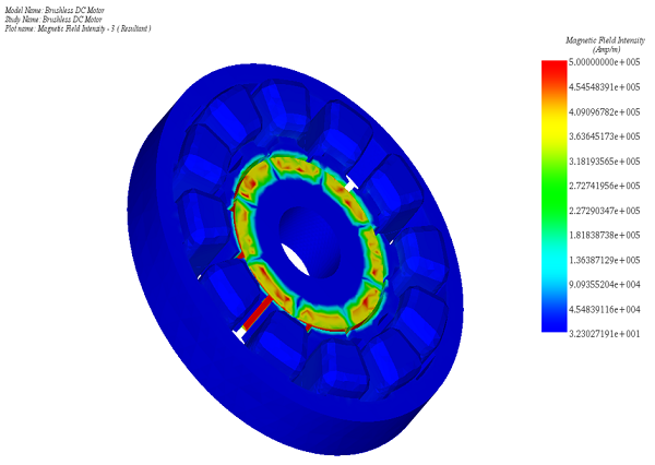
Figure 7 - Magnetic Field Intensity, fringe plot
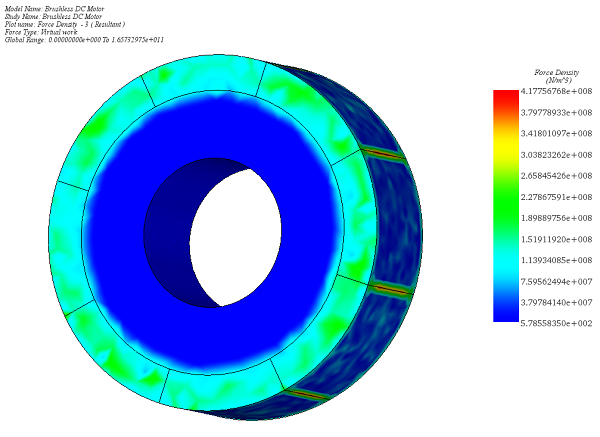
Figure 8 - Force density in the magnets and rotor
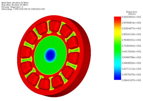
Figure 9- Temperature distribution in the motor with inner air
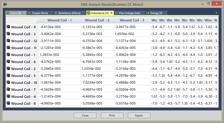
Figure 10 - Results table
Conclusion
The application note details the principles and applications of Brushless DC (BLDC) motors, emphasizing their efficiency, reliability, and broad application spectrum. BLDC motors, free from brushes and commutators, leverage magnet-bearing rotors and sophisticated electronics for performance optimization. These motors find extensive use in various sectors, including automotive, industrial automation, healthcare, and consumer electronics, due to their efficiency and durability. The study conducted using EMS focuses on a BLDC motor featuring an 8-magnet rotor and a 12-coil stator, exploring magnetic flux, coil inductance, and electromagnetic force to enhance motor performance. Key steps in the Magnetostatic analysis—material assignment, boundary condition application, meshing, and solver execution—are meticulously outlined. Coupling Magnetostatic with thermal simulation provides additional insights into motor operation, particularly thermal behavior. The comprehensive simulation results, including magnetic flux density, field intensity, force density, and temperature distribution, underscore the potential of BLDC motors to achieve high efficiency and performance across a wide range of applications.