Permanent Magnet Linear Electric Motor
A linear power system, where a linear machine is driven directly by a free piston engine (FPE), is one of the promising technologies that offer scalability and wide-range applicability. The permanent magnet (PM) based linear electric motor can achieve high acceleration rates and long travel lengths with good thrust forces and extremely high positioning accuracies. They have been increasingly applied to different market sectors and proved their efficiency in various electromechanical systems such as electrical vehicles (EVs), travelators, robotics, and several other industrial applications.
Fig. 1. PM Linear Electric Generator (a Grabcad Image)
EMWorks2D Solution for PM Linear Machine Designs
The transient magnetic module of EMWorks2D, coupled to translational motion, is used to solve the cogging force, no-load, and on-load analyses of the studied linear PM motor designs, which are defined as follows:
-
12 slots/8 poles single-side flat linear electric motor design
-
6 slots/4 poles tubular linear electric generator design
12Slots/8 Poles Linear Electric Motor Design
Design Details:
The first studied design is a three-phase linear motor made of 8 poles and 12 slots mover as shown in figure 2. The mover slot is wounded in a single-layer three-phase winding configuration having a wire diameter of 2.4 mm. The main motor parameters are shown in Table I.
| Parameter | Value |
| Mechanical velocity (m/s) | 0.6 |
| Poles/slots number | 8/12 |
| Frequency (Hz) | 50 |
| Coil turn number | 20 |
| Air gap(mm) | 1 |
Table 1. Motor Parameters

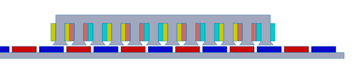
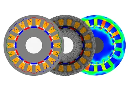
Fig. 2. 2D Design Simplification of 12S/8P PM Linear Electric Motor
Simulation and Results
Detent Force Analysis:
The detent force, or cogging force too, is an important motor performance parameter that can be obtained via a no-load analysis. It is defined as the force that is caused by the attraction between the permanent magnet (PM) and the iron core slots without any input current. The following plot shows the detent force curve of the studied linear motor design versus distance which achieves a maximum value of 135 N.
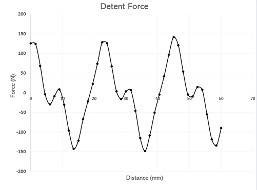
Fig. 3. Detent Force Versus Distance
No-Load Analysis:
Through the no-load analysis, the back EMF and flux linkage are computed at the defined speed of 0.6 m/s. The back emf of the studied machine reaches a magnitude value of 7.5V and presents large waveforms for all three phases.
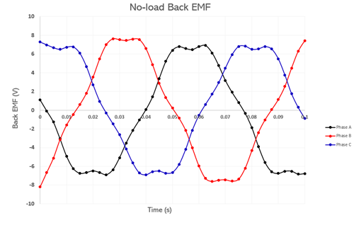
Fig. 4. Back EMF Plot Versus Time
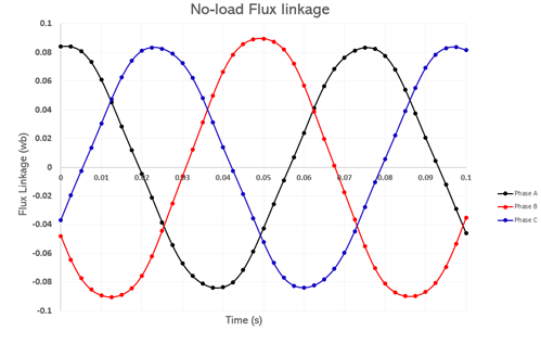
Fig. 5. Flux Linkage Plot Versus Time
On-Load Analysis:
The third analysis is dedicated to the on-load case, where the capability of thrust force generation of the studied machine is investigated. During the translational motion, the accelerated mass of the mover generates a force of equal magnitude, called thrust force, but in the opposite direction to be applied to that system. The obtained thrust force curve versus time is shown in the following figure:
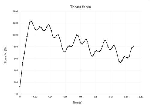
Fig. 6. Thrust Force Variation Versus Distance
For an input three-phase sinusoidal voltage of 15 V magnitude, the studied PM Linear motor design generates the following current results which achieve a maximum value of 120 A over the three system phases.
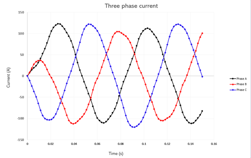
Fig. 7. Three-Phase Current Curves Versus Time
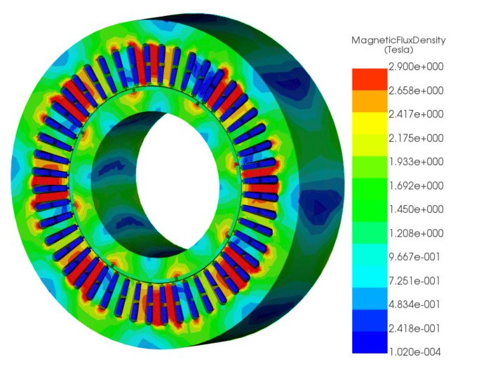
The magnetic flux density animation plot versus time is plotted as well and shown below:
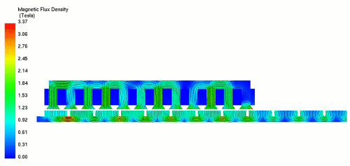
Fig. 8. Magnetic Flux Density Animation Versus Motor Displacement
6 Slots/4 Poles Tubular Linear Electric Generator Design
Design Details:
The second studied design is a three-phase tubular generator design made of 4 poles mover and 12 slots stator as shown in figure 3. Thanks to the axisymmetric invariance characteristic of the studied generator, the 3D design is simplified using EMWorks2D which helps to shorten the simulation time. The main motor parameters are shown in Table 2.
| Parameter | Value |
| Mechanical velocity (m/s) | 2.75 |
| Poles/Slots number | 4/6 |
| Frequency (Hz) | 50 |
| Coil turn number | 76 |
| Air gap(mm) | 2 |
Table 2. Motor Parameters
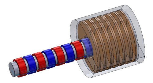
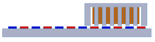
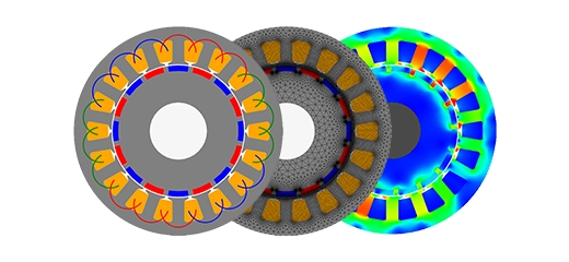
Fig. 9. 2D and 3D Designs of the 6S/4P PM tubular generator
Simulation and Results
Following the same analysis steps done for the PM Linear motor, the 2D simulation of the tubular generator machine revealed the following results for no-load and on-load analyses:
Detent Force Analysis:
The detent force curve of the generator design is shown in Fig.10 which achieves a maximum value of 200N.
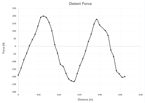
Fig. 10. Detent Force Versus Distance
No-Load analysis:
The three-phase back EMF curves show more sinusoidal waveforms than the previously studied motor design. They achieve a higher voltage value of 105 V during one time period of 20 ms. The second figure is showing the flux linkage curves with a maximum value of 0.35 Wb for the three phases.
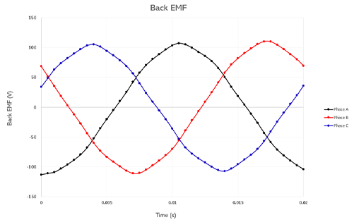
Fig. 11. Three-Phase Back EMF Curves Versus Time
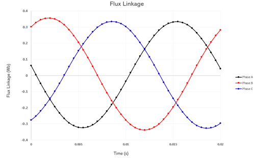
Fig. 12. Three-Phase Flux Linkage Curves Versus Time
On-Load Analysis:
An on-load generator analysis, using the EMWorks2D integrated circuit simulator, allowed the coupling of the studied generator with a fully resistive three-phase load. The obtained thrust force x-direction curve and magnetic flux density animation are shown below.
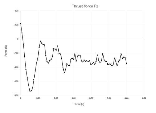
Fig. 13. Thrust Force Plot Versus Time
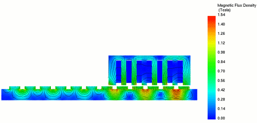
Fig. 14. Magnetic Flux Density Animation Versus Mover Displacement
The generated current is shown in Figure 13 which reaches a maximum magnitude of 12A for the translating velocity of 2.75 m/s.
The corresponding current density plot versus the time of the tubular generator is shown by the animation plot in Figure 14, which displays the variation of the three-phase winding current density during the linear motion of the PM mover.
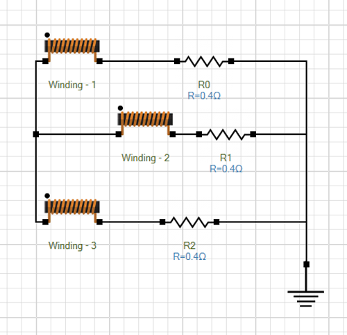
Fig. 15. On-Load Generator Circuit-Resistive Load
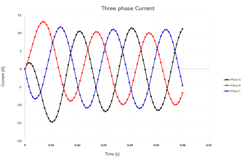
Fig. 16. Three-Phase Current Curves Versus Time
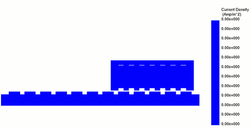
Fig. 17. Current Density Animation Versus Mover Displacement
Loss analysis of the PM generator includes both core and winding loss types, allowed to plot their variation versus time in the figures below. As noticed, the total core loss results in the iron back and stator parts being neglected compared to the winding loss result which achieves an average value of 200W compared to the core losses.
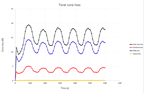
Fig. 18. Core Loss Curves Versus Time
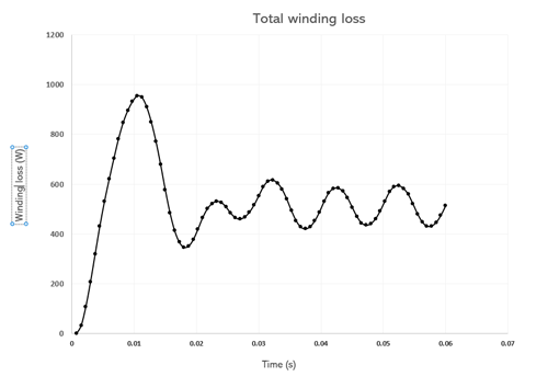
Fig. 19. Winding Loss Curve Versus Time
Consequently, the obtained temperature results achieve higher heat rates across the stator and winding part with a maximum value of 45 °C compared to an increase of only 0.6 °C over the ambient temperature on the PM mover side.
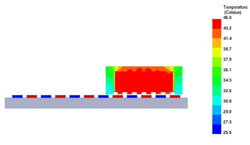
Fig. 20. Temperature Distribution Across Stator
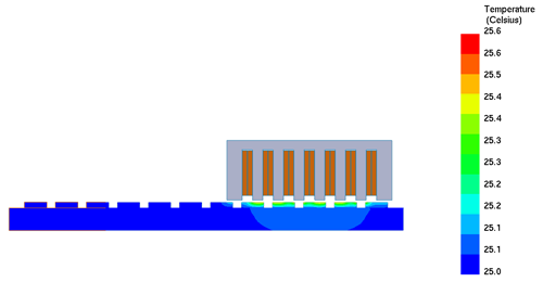
Fig. 21. Temperature Distribution Across the Mover
Conclusion
In this application note, two linear electric machine designs are investigated for both motor and generator modes. The electromagnetic performances such as detent and thrust forces, back emf, output current, flux linkage, and field densities are plotted and analyzed using EMWorks2D simulation. A loss and thermal analyses were performed for the PM tubular generator design which allowed us to study the machine's behavior when exposed to high winding loss amounts.