A Halbach Array Permanent Magnet Motor
Halbach array PM motors enhance electromagnetic machinery with higher power and torque density, offering a stronger magnetic field for the same PM volume. These motors are increasingly popular in sectors like aerospace, industrial, and healthcare, thanks to their superior performance and efficiency.
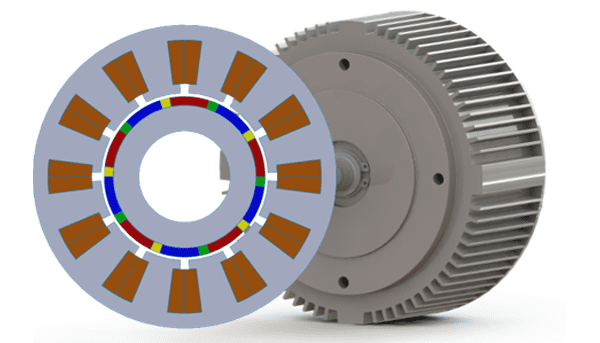
Figure 1- PM Halbach array motor
Magnet Ratio Computation (Rmp)
Rmp is defined as the ratio of the pole arc for the radial PM components βr, to pole pitch of a single pole βm, as follows,
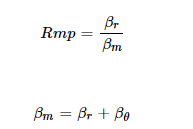
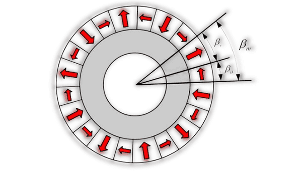
Figure 2a- PM Halbach array configuration
EMWorks2D Solution
The transient magnetic analysis, coupled with rotational motion, is used to solve the cogging torque, no-load, and on-load analyses of the PM motor design. Three different PM configurations are presented in this study, based on the value of Rmp of 1, 0.8, and 0.5.
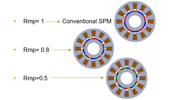
Figure 2b- PM Halbach array configuration with Rmp = 1, 0.8, and 0.5
Design Specifications
The following table summarizes the main design specifications of the PM Halbach array motor:
| Design parameter | Value |
| Number of phases | 3 |
| Number of slots/poles | 12/10 |
| Frequency (Hz) | 50 |
| Base speed (rpm) | 400 |
| Coil turn number | 35 |
| Air gap length (mm) | 1 |
Simulation and Results
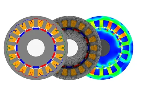
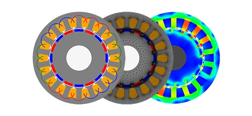
In this section, different analyses are performed using EMWorks2D software to evaluate the performance of the machine for the three PM configurations. Figure 3 illustrates the 2D CAD models of the three motors.
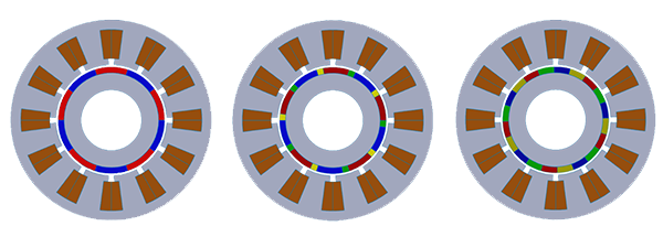
Figure 3- PM Halbach array motor designs with Rmp = 1, 0.8, and 0.5
Cogging Torque Analysis
The cogging torque, one of the important motor performance parameters, can be obtained at a no-load analysis. The following plot shows the cogging torque curves for the three PM configurations for one electrical period. As shown in Figure 4, the conventional PM motor design -non-Halbach- produces a higher cogging torque compared to the case of Halbach with a smaller magnet ratio.
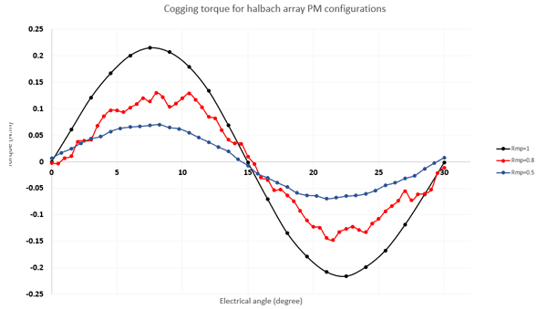
Figure 4- Cogging torques versus electrical angle
No-Load analysis
Using a no-load analysis, the back EMF and magnet coil flux linkage are computed at the desired base speed of 400 rpm. Figure 5 shows the magnetization direction for each PM configuration using the vector plot of the magnetic flux density.
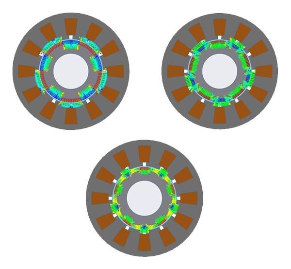
Figure 5- Vector plot of magnetic flux density due to PM
The back EMF curves for each configuration are superimposed and compared in Figure 6. Clearly, the back EMF for the smallest Rmp value is more sinusoidal compared to the conventional PM design and the Halbach array PM design with Rmp = 0.8.
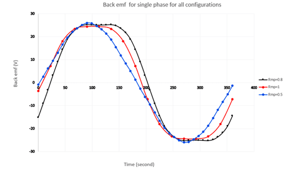
Figure 6- Back EMF variation versus time for all three configurations
On-Load analysis
The second part of the simulation results is dedicated to the on-load study, where the capability of torque generation of the machine with three-phase sinusoidal voltage excitation to the windings at the frequency of 50 Hz is presented.
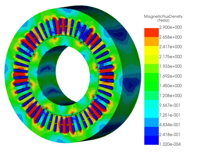
The magnetic flux density animation plots versus time are shown below for each configuration.
Figure 7- Magnetic flux density animations versus time for Rmp=1, 0.8, 0.5
The comparison of the on-load electromagnetic torque among the different machine designs is shown in the Figure 8. The PM design with Rmp = 0.8 presents the highest torque compared to the rest of the configurations. In addition, it is important to note that the relation between magnet ratio and motor torque is not linear since the torque for the 0.5 ratio presents the smallest torque.
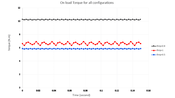
Figure 8- Comparison of on-load electromagnetic torque versus time for Rmp=1, 0.8, 0.5
Conclusion
The following table summarizes the simulated results obtained for each PM motor configuration. It can be concluded that for the same amount of PM volume and at the same base speed, the Halbach PM configuration with a 0.8 magnet ratio presents the highest average electromagnetic torque and torque density. The obtained results demonstrate that the optimization process of the Halbach PM motor design for electromagnetic torque is not linear concerning the magnet ratio.
 |  |  | |
|---|---|---|---|
| Parameter | Rpm=1 | Rpm=0.8 | Rpm=0.5 |
| Torque (N.m) | 6.65 | 10.1 | 5.85 |
| Speed Ns (rpm) | 400 | 400 | 400 |
| Power (Watt) | 278.55 | 423.07 | 245 |
| Torque density (kN.m/m3) | 9.478 | 14.395 | 8.337 |