Introduction
The simplicity, affordability, and high torque/power density of Permanent Magnet assisted switched reluctance motors have made them highly desirable for various drive applications. This application note provides an evaluation and comparison between a segmented SRM and a segmented-stator PM-assisted SRM machine, focusing on their static magnetic and dynamic performances.
Characteristics like simple structure, high starting torque, low manufacturing cost, fault tolerance, and wide speed range in constant power operation, make the SRM a good choice for many industrial applications. However, it also suffers from some disadvantages, such as low torque and power densities, high torque ripple, and acoustic noise compared with other PM machines.
Simulation Geometry
Several modular structures have been suggested for improving the performance of SRMs, with a specific focus on enhancing lighter weight and achieving higher power/torque density.
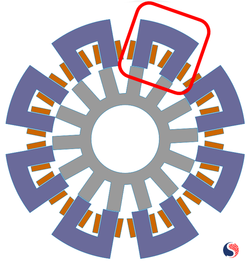
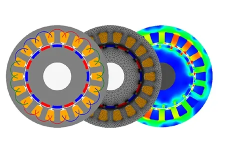
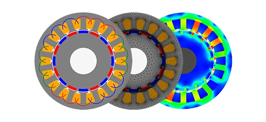
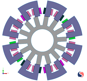
Fig. 1. Segmented SRM
Segmented stator or modular stator SRMs feature a new design where the stator core is divided into several segments, each with its own set of windings. This modular arrangement provides the opportunity to use lower material volume in production. Furthermore, having a segmented stator with independent windings will help to have easier maintenance and replacement.
In this application note, two segmented SRMs are compared. In one model a permanent magnet is added in the slot opening to enhance the performance.
 |
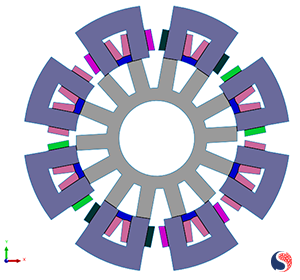 |
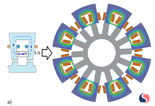
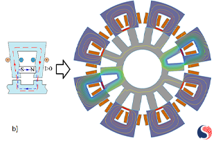
| Fig. 2. (a) 4-Phase 16/14 SRM Motor | Fig. 2. (b) Permanent Assisted 4-Phase 16/14 SRM Motor |
In Figure 2, the machine topologies of the 16/14 segmented-stator permanent-magnet-assisted SRM and the 16/14 conventional SRM are depicted. Both SRMs have the same rotor configuration with 14 salient poles and without any PMs or coils. However, the stator topologies differ between the two machines. The segmented SRM stator consists of eight individual U-shaped electrical steel laminated segments, each having two teeth where the armature winding coils are wound. In the proposed topology, each stator segment also contains a PM inserted between two poles. On the other hand, the segmented SRM lacks yoke iron or other ferromagnetic material in the slot opening, resulting in eight evenly arranged segments along the rotor, each with its own independent magnetic structure. The stator poles are twisted with 16 coils, divided into phases A, B, C, and D.
 |
 |
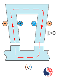 |
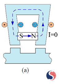
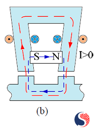
| Fig. 3. (a) The Magnetic Circuit: Magnetic Field without Excitation | Fig. 3. (b) The Magnetic Circuit: Magnetic Field with Current Excitation | Fig. 3. (c) The Magnetic Circuit: Magnetic Field with Current Excitation without Magnet |
In Figure 3 (a), the magnetic circuit in one segment of the pm-assisted SRM is displayed when none of the coils are powered in the aligned position. The PM-generated flux is confined to the U-shaped segment and does not pass through the rotor core and air gap. Figure 3 (b) illustrates the magnetic circuit of the segment when the coils are excited with current. Here, it can be observed that the flux generated by the coils and the PM are combined, both flowing in the same direction in the rotor teeth and air gap. As a result, the total magnetic flux generates a greater electromagnetic attraction force compared to a conventional SRM. Figure 3 (c) shows the magnetic circuit of a modular electromagnet when the coils are excited in the aligned position.
Simulation Settings and Results
The simulations have been successfully conducted using the EMWORKS2D software in the transient magnetic study. All materials utilized in the parts have been selected from the default software library, and their details can be found in Table1.
| Machine part | Material |
| Rotor and Stator | Electrical Steel – M300-35A |
| Windings | Copper |
| Magnets | NdFeB – N4212 |
| Environment | Air |
Table 1. Material Characteristics
Geometric and excitation simulation parameters are listed in Table 2.
| Parameters | Segmented SRM | PM-Assisted Segmented SRM |
| Phase number | 4 | 4 |
| Stator and rotor poles | 16/14 | 16/14 |
| Rated power | 426 | 445 |
| Rated speed (r/min) | 600 | 600 |
| Output torque (N·m) | 6.79 | 7.07 |
| Stator outer diameter (mm) | 230 | 230 |
| Axial length (mm) | 50 | 50 |
| Number of coils turns per pole | 114 | 114 |
| Stator rotor embrace | 0.55 | 0.55 |
| Input current | 6A | 6A |
Table 2. Geometric Characteristics
Flux line distribution in the pm-assisted motor with and without the phase excitation is depicted here in Figure 4 to prove the design concept simulation validation.
 |
 |
| Fig. 4. (a) Flux Distribution of PM-Assisted Motor: without Excitation | Fig. 4. (b) Flux Distribution of PM-Assisted Motor: with Current Excitation in Phase A |
To enhance the understanding of the field distribution, a captivating animation is prepared that vividly demonstrates the temporal changes in the field.
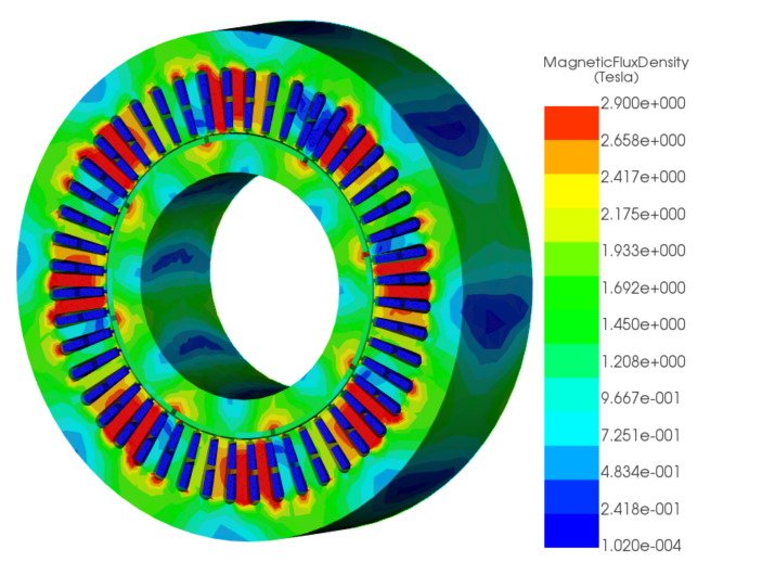
Fig. 5. Magnetic Flux Density Distribution
Finally, the comparison focuses on the crucial output of the machine: the mechanical torque between the motor with a permanent magnet and the motor without one. It's important to note that both motors had the same geometry and excitation settings throughout the comparison.
Figure 6 indicates that the average torque of the PM-assisted motor surpasses that of the other motor. Additionally, the maximum and minimum values demonstrate a reduction in torque ripple within this particular design.
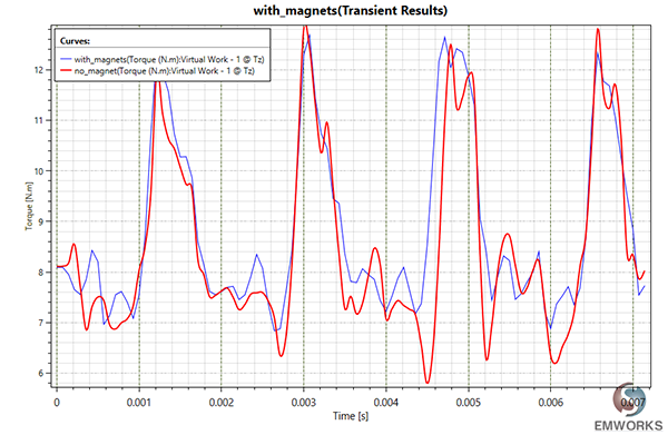
Fig. 6. Output Torque
Conclusion
In conclusion, this application note has presented a comprehensive comparison between a segmented PM-assisted SRM and its counterpart with no magnets in the stator. The stator of the machine was divided into eight distinct U-shaped segments, each featuring two teeth with placed permanent magnets (PM) within the slot openings. Extensive analysis of the magnetic properties, including flux distribution and electromagnetic torque, was conducted for both configurations. The findings demonstrate that the integration of permanent magnets within the stator yields remarkable improvements across various critical parameters. These enhancements encompass reduced iron consumption, heightened average torque under static and dynamic conditions, diminished torque ripple, increase in power and torque densities, and overall enhanced efficiency.
References
[1] W. Ding, S. Yang and Y. Hu, "Development and investigation on segmented-stator hybrid-excitation switched reluctance machines with different rotor pole numbers", IEEE Trans. Ind. Electron., vol. 65, no. 5, pp. 3784-3794, May 2018.
[2] S. R. Mousavi-Aghdam, M. R. Feyzi, N. Bianchi and M. Morandin, "Design and analysis of a novel high-torque stator-segmented SRM", IEEE Trans. Ind. Electron., vol. 63, no. 3, pp. 1458-1466, Mar. 2016.
[3] L. Szabo and M. Ruba, "Segmental stator switched reluctance machine for safety-critical applications", IEEE Trans. Ind. Appl., vol. 48, no. 6, pp. 2223-2229, Nov. 2012.