Transformer
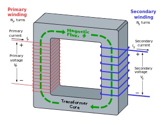
Transformers are vital electrical devices that efficiently transfer energy between circuits via electromagnetic induction. They consist of core, primary, and secondary windings. Operating on electromagnetic induction principles, a varying current in the primary winding induces a magnetic field in the core, generating voltage in the secondary winding by Faraday's law. This process enables power transfer without direct contact. Transformers play a crucial role in stepping up/down voltage levels, facilitating long-distance electricity transmission with minimal losses. They are essential in power generation, transmission, and distribution, ensuring reliable energy availability in modern electrical systems.
Applications of transformers
Transformers are essential in managing AC voltage levels, serving critical roles in power transmission, distribution, and electronic applications. They regulate voltage for efficient energy transfer, enabling electricity generation, long-distance transmission, and safe distribution. In electronics, they vary in size to suit different needs, from compact RF transformers for high-frequency circuits to large power transformers for grid interconnection. Their efficiency and versatility make them indispensable in diverse electrical systems, ensuring reliable energy delivery and enabling the effective operation of electronic devices.
Losses in transformers
There are 2 main kinds of losses in a transformer that are useful for engineers.
-
Core loss
-
Winding loss
A well-executed transformer design aims to minimize losses, verified through open circuit and short circuit tests on physical prototypes. These tests not only quantify losses but also establish an equivalent circuit model for simulations. By integrating this model into system-level simulations, engineers can analyze the transformer's performance within the broader electrical system context. This streamlined approach enables comprehensive evaluations, optimizing efficiency and minimizing losses. Ultimately, it ensures the transformer operates efficiently, enhancing the overall performance and reliability of the electrical system.
Open circuit test
The open circuit test, illustrated in Figure 2, assesses core loss in a transformer. Conducted with one winding, typically the high-voltage side left unloaded, it gradually increases the voltage on the low-voltage winding until reaching its rated voltage. A wattmeter on the low-voltage circuit measures input power, representing core loss. This test gauges the power dissipated in the transformer's core under rated low-voltage conditions. Crucial for evaluating efficiency and performance, especially in terms of losses, it's a fundamental step in transformer design and testing.
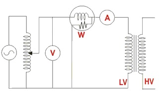
Figure 2 - Open circuit test
Short circuit test
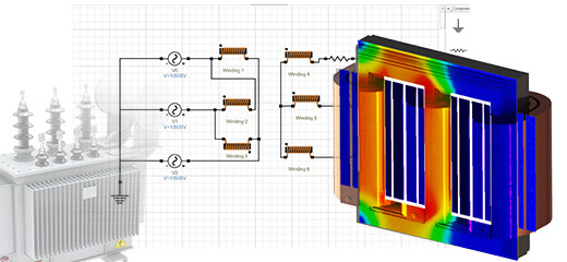
Figure 3 depicts the connection diagram for the short circuit test on a transformer. Here, the low-voltage side is intentionally short-circuited, while the high-voltage side's voltage is gradually increased until reaching its rated current. A wattmeter measures the consumed power, approximating copper loss. This test evaluates power dissipation in the transformer's windings due to their resistance under low-voltage short circuit conditions. Vital for determining copper losses, and crucial for assessing efficiency and performance, these test results aid in creating an equivalent circuit and conducting system-level simulations for the transformer.
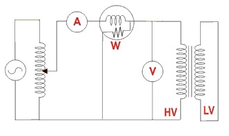
Figure 3 - Short circuit test
Open circuit test and short circuit test simulation
Simulation in EMS offers a compelling advantage by enabling engineers to conduct both open-circuit and short-circuit tests virtually. When performing the open circuit test using EMS, several essential input parameters are necessary to accurately simulate the test conditions.
-
Material property of the core – the B-H curve of the steel material, lamination details, Core loss curve for the laminate (P-B curve)
-
Rated voltage in the Low Voltage side must be applied to the low voltage winding
-
The high voltage side must be kept open i.e. a current equal to 0 Amps must be applied to the high voltage winding
Upon completion of the simulation, EMS provides valuable outputs such as core loss and low voltage side current. To conduct the short circuit test simulation effectively in EMS, certain inputs need to be defined. Specifically:
-
The low voltage side should be shorted, requiring the application of a 0 voltage across the low voltage winding.
-
The high-voltage winding should have varying voltages applied while measuring the current until it reaches the rated current on the high-voltage side. EMS allows for parametric simulations, facilitating the adjustment of applied voltage and measurement of current. The voltage value that achieves the rated current can then be selected for the short circuit simulation.
This approach streamlines the short circuit test simulation process within EMS.
Upon completing the simulation in EMS for both the open circuit and short circuit tests, several critical parameters are provided as outputs. These results are fundamental in constructing the equivalent circuit of the transformer and gaining insights into its performance. Here is a brief overview of the modeling process within EMS and a discussion of the obtained results:
-
CAD Model: Figure 4 illustrates the CAD model that serves as the basis for simulation.
-
Laminate Material: Figure 5 depicts the material properties assigned to the laminate used in the transformer.
-
Coil Definition: Figure 6 showcases the definition of the coil inside EMS, a crucial component for electromagnetic analysis.
-
Separate Studies: In EMS, each test (open circuit and short circuit) is conducted as a distinct study to ensure accurate and specific results.
-
Result Table: Figure 7 displays the result table, which provides essential data from the simulations.
-
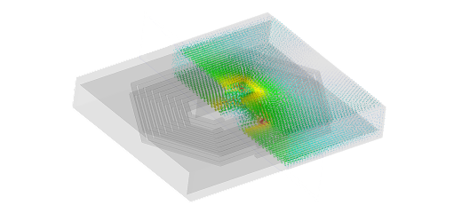
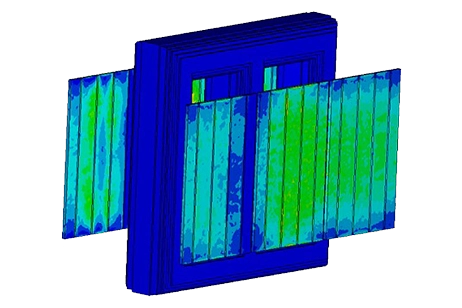
Magnetic Flux Density: Figure 8 presents a section plot of the magnetic flux density obtained during the open circuit test, offering valuable insights into the transformer's electromagnetic behavior.
This comprehensive approach in EMS enables engineers to derive crucial information for transformer design and optimization, including copper loss, leakage inductance, and winding resistance. These results are instrumental in creating the equivalent circuit for the transformer.
Discussion of results including equivalent circuit
This section provides a concise overview of the modeling process in EMS and presents the key results obtained from the simulations. Here's a summary of the content covered:
-
CAD Model (Figure 4): The simulation begins with the creation of a CAD model, which serves as the foundation for electromagnetic analysis.
-
Laminate Material (Figure 5): Figure 5 illustrates the material properties assigned to the laminate material used in the transformer, ensuring an accurate representation of its behavior.
-
Coil Definition in EMS (Figure 6): Figure 6 showcases the coil definition within EMS, a critical component for accurately modeling electromagnetic interactions.
-
Open and Short Circuit Simulations: Both the open circuit and short circuit tests are conducted, and the results from each test are discussed separately.
-
Separate Studies: EMS performs each test as a distinct study, allowing for precise analysis and a comprehensive understanding of the transformer's behavior.
-
Result Table (Figure 7): Figure 7 displays a result table that provides essential data and parameters obtained from the simulations, aiding in transformer evaluation.
-
Magnetic Flux Density (Figure 8): A section plot of the magnetic flux density during the open circuit test (Figure 8) is presented, offering insights into the transformer's electromagnetic performance.
This approach within EMS enables engineers to gain valuable insights into the transformer's behavior and performance, facilitating informed design decisions and optimization.
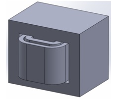
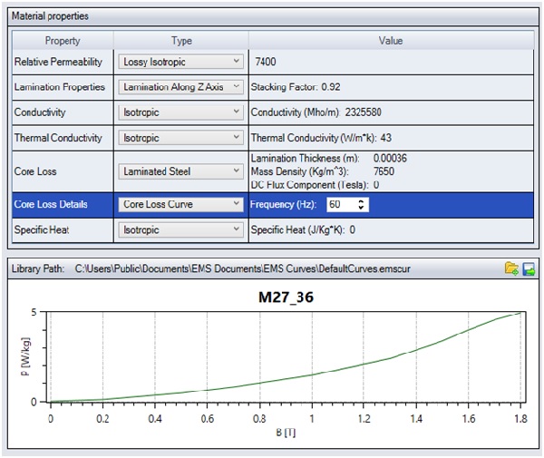
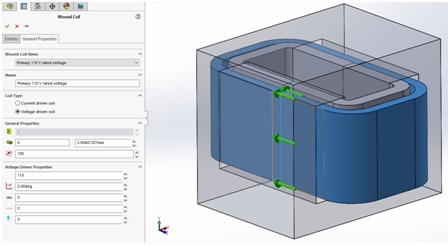
Figure 6 - Coil definition inside EMS
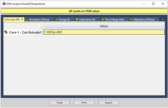
Figure 7 - Result table contains all the results including the Core Loss
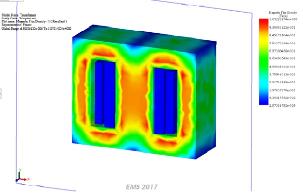
Figure 8 - Section plot of the magnetic flux density
Conclusion
The application note delves into the critical role of transformers in electrical systems, elucidating their function in efficiently transferring energy between circuits through electromagnetic induction. Transformers, comprising core, primary, and secondary windings, operate by inducing a voltage in the secondary winding via a time-varying magnetic field generated by the primary winding. These devices are indispensable for stepping up/down voltage levels, enabling electricity transmission over long distances with minimal losses. Furthermore, they find extensive applications in various sectors, from power generation to electronics, due to their ability to regulate voltage effectively. The note outlines two key tests, the open circuit, and short circuit tests, essential for evaluating transformer performance and minimizing losses. By simulating these tests virtually using EMS, engineers can optimize transformer designs and assess their behavior within complex electrical systems accurately. The EMS simulations provide valuable insights into core loss, winding resistance, and overall performance, guiding informed design decisions for efficient and reliable transformer operation.
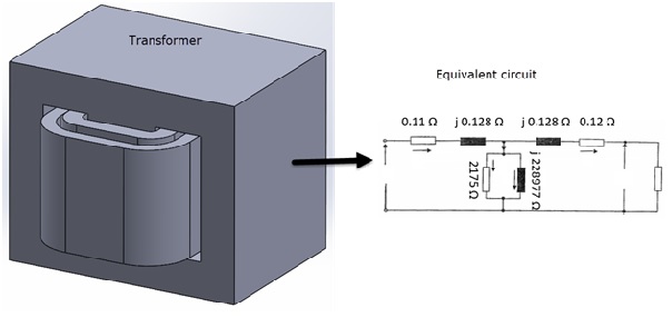
Figure 9 - Equivalent circuit of the transformer