

AC transformer
The AC transformer is crucial for modifying voltage in AC circuits, providing a key advantage in power distribution by facilitating easier voltage adjustments compared to DC systems. This capability is particularly beneficial for long-distance power transmission, where high voltage and low current configurations minimize resistive losses and allow for the use of thinner, less costly wires.
CAD model of an AC transformer
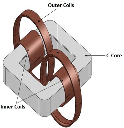
Figure 1 - 3D model of the AC transformer
EMS Simulation of an AC Transformer
In EMS simulations, AC transformers undergo an AC Magnetic study to determine core losses and other electromagnetic characteristics, with a standard testing frequency set at 50 Hz. This analysis helps in assessing the transformer's efficiency and performance under typical operating conditions.
Material
The simulation model for an AC transformer includes several components: a core, two sets of coils (inner and outer), and designated air spaces surrounding these coils to model the insulation and cooling gaps. Material properties for each component—such as the core's permeability and the coils' electrical conductivity—are detailed to accurately simulate electromagnetic behavior, enhancing the model's precision in calculating core loss and other electromagnetic results.
Table 1 - Materials used in the EMS simulation
| Component | Material | Relative permeability | Electrical Conductivity (S/m) |
| C-Core | Steel 1 | 5000 | 1.030e+007 |
| Inner Coils/ Outer Coils | Copper | 0.99991 | 5.7e+007 |
| Inner Air, Outer Air | Air | 1 | 0 |
Coils
The simulation models the inner and outer coils as wound components operating at a frequency of 50 Hz. This setup helps in analyzing how current flows through these coils, with specific properties like the number of turns and current magnitude crucial for understanding their performance. The detailed configuration aids in assessing the transformer's efficiency and electromagnetic interactions.
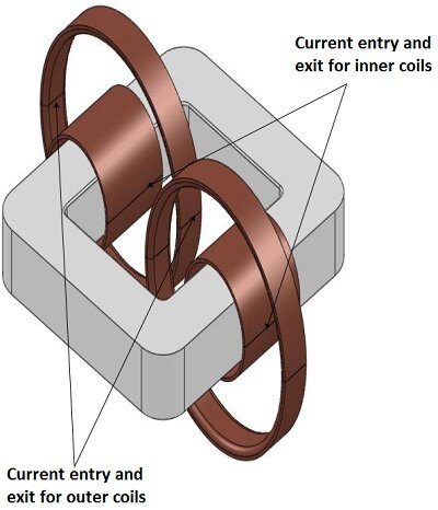
Table 2 - Coils information
| Name | Number of turns | Current Magnitude (RMS) | Current Phase |
| Inner Coils (primary) | 21 | 15.5 A | 0 deg |
| Outer Coils (Secondary) | 22 | 15.5 A | 0 deg |
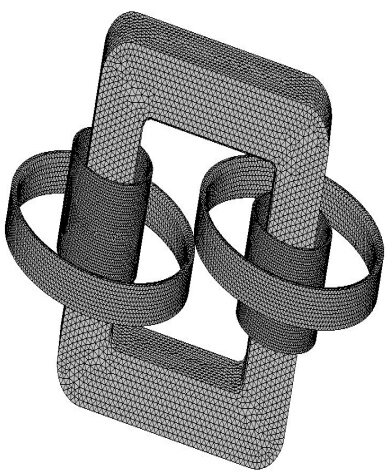
Meshing
Meshing significantly impacts the precision of design analysis in EMS by determining the element size based on the model's volume, surface, and geometric details. Applying mesh control to specify varying element sizes across different model regions enhances result accuracy, with smaller sizes improving detail in critical areas. This strategy is visualized in the meshed model illustration, demonstrating the tailored approach to meshing for optimal simulation outcomes.
Table 2 - Mesh control
| Name | Mesh size | Components /Bodies |
| Mesh control 1 | 10.00 mm | C-Core |
| Mesh control 2 | 5.00 mm | Inner Coils |
| Mesh control 3 | 7.00 mm | Outer Coils |
| Mesh control 4 | 20.00 mm | Inner Air |
Results
In the AC Magnetic study by EMS, various parameters such as magnetic flux density, field intensity, and electric field, among others, are analyzed to understand the transformer's performance. Specifically, losses like Ohmic, Eddy, Hysteresis, Excess, and Core loss within the C-Core are calculated, providing insights into efficiency and areas for improvement. These metrics are crucial for optimizing transformer design and functionality.
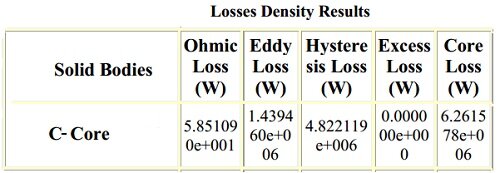
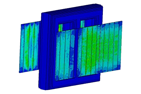
Figure 4 - Losses density results
3D fields generated by EMS
EMS generates detailed 3D visualizations for analyzing an AC transformer's performance, including magnetic flux density, current density, and core loss. These plots, illustrated in subsequent figures, offer a comprehensive view of the electromagnetic phenomena within the transformer, aiding in the evaluation and optimization of its design.
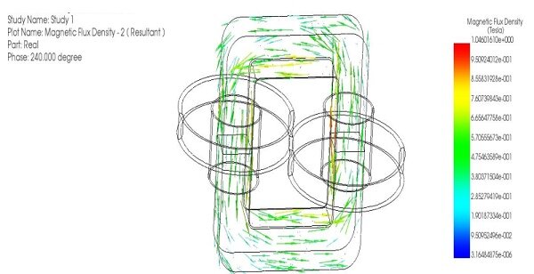
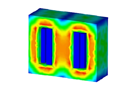
Figure 5 - Magnetic flux density
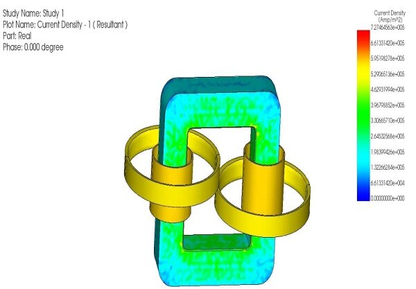
Figure 6 - Current density distribution
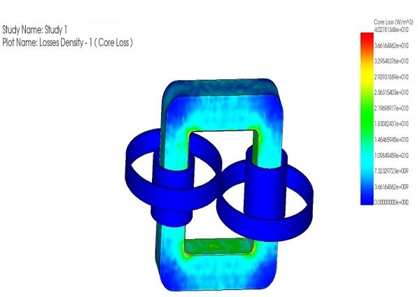
Figure 7 - Core loss in the transformer
Conclusion
The AC transformer plays a vital role in modifying voltage for efficient power distribution in AC circuits, offering advantages like easier voltage adjustments compared to DC systems. Through EMS simulations, its electromagnetic characteristics, core losses, and efficiency are assessed, crucial for optimizing its design. The CAD model showcases the transformer's core-coil arrangement, while detailed material properties ensure accurate electromagnetic behavior simulation. The study also highlights the importance of meshing for precise analysis and tailoring mesh sizes to different model regions. Results from the AC Magnetic study provide insights into losses and electromagnetic phenomena, aiding in design evaluation and optimization. Overall, this comprehensive approach to AC transformer analysis guides improvements for enhanced efficiency and performance in power distribution systems.

-(1).webp)