A High-Power Transformer
In this application note, EMS is used to study both the electromagnetic and structural behavior of a high-power transformer. Both AC Magnetic and structural solvers of EMS are used to compute the magnetic and structural results. The impact of the magnetic shunts utilized to protect the outer tank is investigated in this analysis.
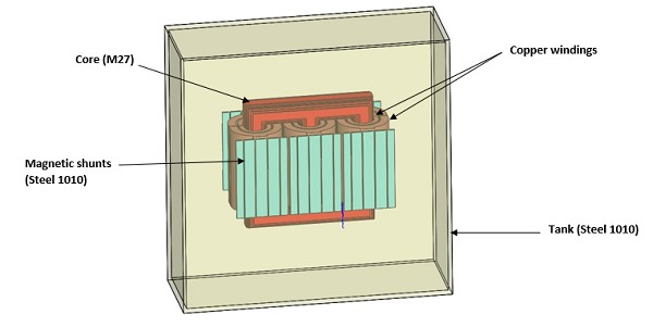
Fig. 1. CAD Model of the Studied Transformer
The EMS coupled with the structural module provides crucial insights into both magnetic and structural aspects. It offers 3D plots for parameters like magnetic field, current distribution, loss density, force density, displacement, and stress. Additionally, it computes essential quantities like inductance, resistance, voltage, current, rigid body force, and losses including core, eddy, hysteresis, and winding losses. This comprehensive analysis aids engineers in optimizing designs for performance and efficiency.
Electromagnetic Results
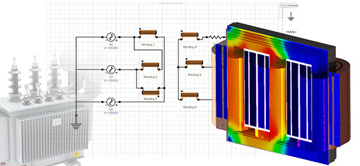
The simulation is conducted under short circuit conditions, utilizing the AC Magnetic solver of EMS to produce the electromagnetic solution. Figure 2 presents the results depicting the magnetic field within the transformer core.
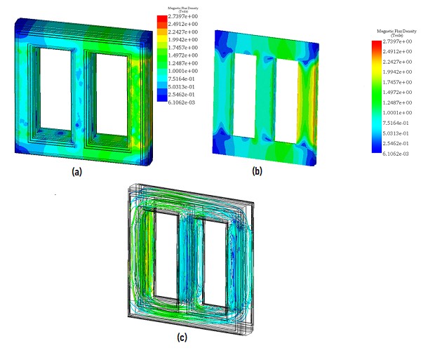
Fig. 2. Magnetic Field Results, a) Full Model - Fringe Plot, b) Cross Section View – Fringe Plot, c) Full Model - Streamline Plot
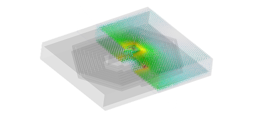
Figures 3a), 3b), and 3c) depict the eddy current results in the outer tank, showcasing the contrast in induced eddy currents with and without the magnetic shunts. These magnetic plates serve to safeguard the tank by diminishing both the eddy currents and the electromagnetic forces. Furthermore, Figure 4 presents a plot illustrating the distribution of eddy currents within the magnetic shields.
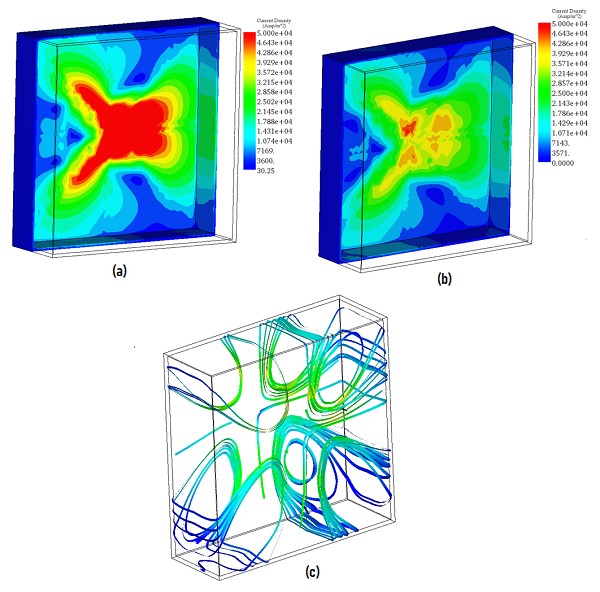
Fig. 3. Eddy Currents Results in the Tank, a) Without Magnetic Shunts, b) With Magnetic Shunts (Hidden), c) Streamline Plot of the Eddy Currents
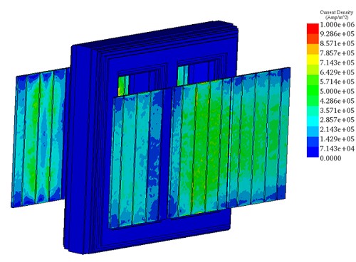
Fig. 4. Eddy Currents in the Magnetic Plates
Table 1 summarises the force results of the transformer under different conditions. It shows that the force in the tank is reduced when the magnetic shunts are added. However, the shunts do not have much impact on the force in the windings.
| Force Results (N) | ||
| Without Magnetic Shunts | With Magnetic Shunts | |
| Tank | 21.32 | 8.12 |
| Transformer Core | 367 | 368 |
| Magnetic shunts | 0 | 28 |
| Primary winding 1 | 1452 | 1432 |
| Primary winding 2 | 1972 | 1993 |
| Primary winding 3 | 2134 | 2116 |
| Secondary winding 1 | 534 | 530 |
| Secondary winding 2 | 54 | 54 |
| Secondary winding 3 | 899 | 895 |
Table 1. Force Results in the Different Parts of the Transformer
Structural Results
Additionally, coupling with the linear static solver within EMS produces the following structural outcomes: structural displacement, mechanical stress, strain, reaction force, and safety factor.
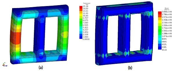
Figures 5a) and 5b) showcase plots of mechanical displacement and stress within the transformer core. Notably, the maximum displacement registers around 15 nanometers in the outer limbs, while stress peaks at approximately 6e4 N/m^2. These mechanical deformations predominantly stem from magnetostriction forces within the core.
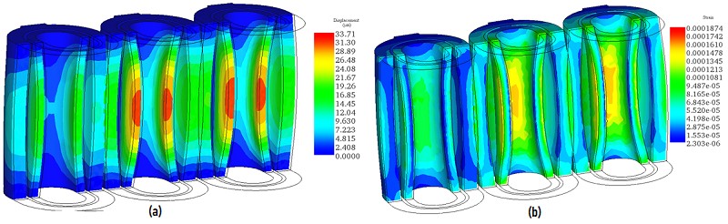
The circulating currents, particularly during a short circuit scenario, induce significant Lorentz forces in the transformer's windings, leading to deformation. Figures 6a) and 6b) display the mechanical displacement and strain in the transformer's windings, with the maximum displacement reaching approximately 33 micrometers.
An interesting observation is that the highest displacement occurs in the inner coils belonging to the low-voltage side of the transformer. The outer coils exhibit a displacement ranging from 19 to 21 micrometers. Although the forces generated on the outer coils are higher (as indicated in Table 1) than those on the inner coils, the displacement is greater in the inner coils. This discrepancy can be attributed to the difference in coil size. The primary windings (outer windings) are larger than the secondary coils, granting them greater rigidity and strength.
Furthermore, it's noteworthy that the displacement in the primary and secondary windings manifests in different directions.
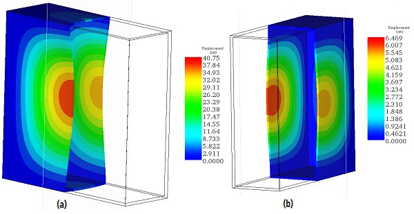
Figures 7a) and 7b) illustrate the displacement results in the transformer tank, respectively, without and with magnetic shunts. It can be observed that the displacement in the tank is around 41 micrometers in the absence of the magnetic shunts. This displacement is estimated by 6 micrometers when the magnetic shunts are used. As mentioned above the magnetic shunts help to decrease the magnetic force in the outer tank and, consequently the mechanical stress and deformation.
The animation plot of the displacement results is shown in Figure 8.
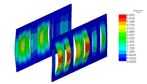
The mechanical displacement in the magnetic shunts is plotted in Figure 9. The magnetic plate deformation is mainly in the range of 2 to 5.6 micrometers.
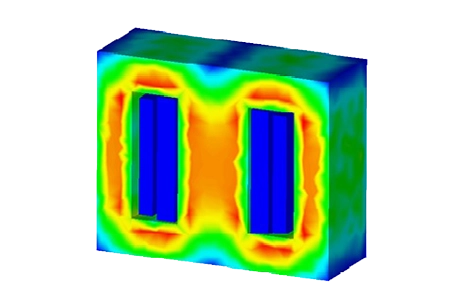
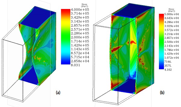
The mechanical stress results in the tank of the transformer are shown in Figure 10. These results confirm the impact of the magnetic shunts. They play an important role in shielding and preventing larger mechanical displacement in the outer tank. This can reduce the vibration and noise caused by the deformations.
Conclusion
In summary, the application note illustrates how EMWorks' electromagnetic simulation software, coupled with structural analysis capabilities, enables a detailed understanding of the interaction between electromagnetic forces and mechanical responses in transformers. By accurately predicting phenomena such as magnetic field distribution, current flow, and mechanical displacement, engineers can optimize transformer designs for improved performance and reliability. The note emphasizes the importance of considering factors like coil size and configuration in analyzing structural deformation under operational stresses, thereby facilitating informed design decisions. Overall, the integration of electromagnetic and structural analyses offers a powerful tool for developing robust and efficient transformer systems.