Magnetic Gear
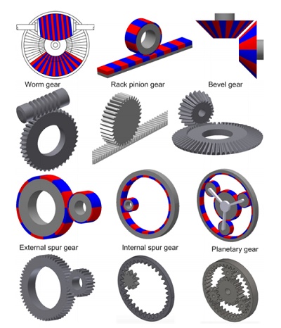
Mechanical gears, traditionally used for speed and torque adjustment in various applications, face issues like friction and noise, impacting their efficiency and reliability. Magnetic gears emerge as a superior alternative, offering frictionless, non-contact power transmission. This innovation leads to reduced maintenance, minimized heat generation, and inherent overload protection, enhancing safety and operational efficiency. They are increasingly favored in applications requiring high safety, clean environments, and efficient power mobility, such as electric vehicles and industrial machinery. With diverse designs like coaxial and parallel axial, magnetic gears represent a significant advancement in gear technology.
Magnetic gears offer benefits but face challenges like size and cost. Efforts aim to enhance torque density and reduce size and costs. The finite element method (FEM) is reliable for engineering system design and analysis, especially in simulating complex geometries. EMWorks2D specializes in magnetic and electric problem-solving, providing accurate 2D solutions. This study uses EMWorks2D to analyze the magnetic properties of two coaxial magnetic gear models, comparing torque results with references for validation.
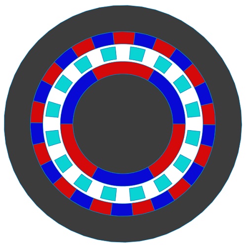
2D simulation of coaxial magnetic gear [2]
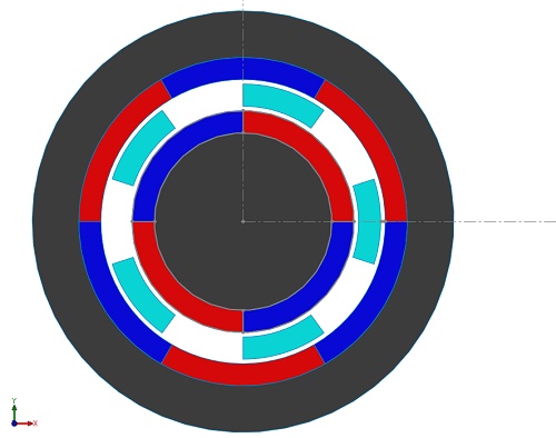
A coaxial magnetic gear model with an inner rotor comprising Pi= 2 pole-pairs and an outer rotor with Po=3 pole-pairs, along with Q=5 ferromagnetic pole-pieces, is detailed in [2]. The inner rotor, termed high-speed (HS), rotates faster than the outer rotor, designated low-speed (LS). Despite the HS rotor's higher speed, the LS rotor generates greater torque. Using EMWorks2D, magnetic flux, and torque are assessed in the air gap region, with end effects disregarded. Iron core permeability is infinite, while magnets possess a remanence of 1.2T and a relative permeability of 1, featuring alternating radial magnetization. Table 1 summarizes the model's key properties, with Figure 2 depicting the 2D model.
| Items | Value |
| Radius of the inner rotor yoke | 40.00 mm |
| Outer radius of the inner rotor PMs | 50.00 mm |
| Inner radius of the slots | 52.00 mm |
| Outer radius of the slots | 62.00 degree |
| Slot opening | 36.00 deg |
| Inner radius of the outer rotor PMs | 64.00 mm |
| Inner radius of the outer rotor yoke | 74.00 mm |
| Axial length | 100.00 |
| Pole-pairs inner rotor | 2 |
| Pole-pairs outer rotor | 3 |
| Ferromagnetic pole-pieces | 5 |
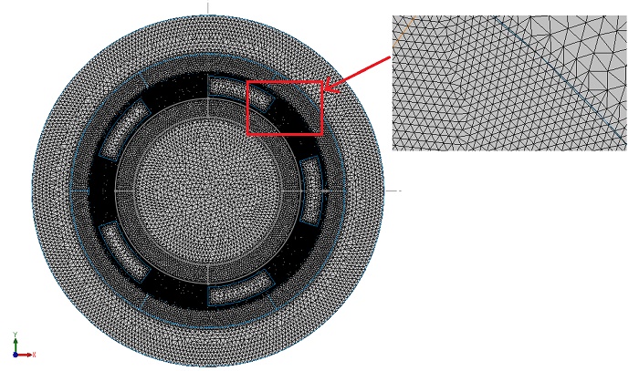
EMWorks2D features an automatic and adaptable mesher, producing triangular mesh elements. Mesh refinement, specifically targeting the air gap region, ensures precision in results. Figure 3 illustrates the mesh plot generated by EMWorks2D.
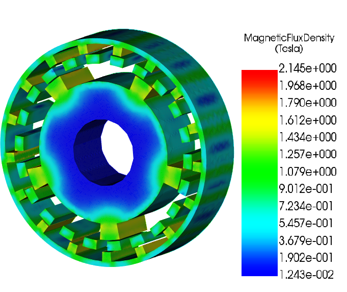
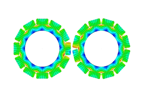
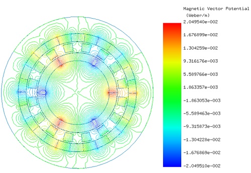
Initially, the LS rotor and ferromagnetic pieces are stationary, while the HS rotor rotates from 0° to 90°. EMWorks2D conducts a parametric sweep to compute magnetic flux and torque relative to the inner rotor angle. Figures 4a) and 4b) show magnetic flux density at $$ \phi_i = 0^\circ $$ and $$ \phi_i = 52^\circ $$ , emphasizing high flux concentrations in the ferromagnetic bodies. Figure 5 displays non-uniform flux density in the air gap at $$ \phi_i = 52^\circ $$, influenced by rotor pole positions. Magnetic vector potential lines in Figure 6 demonstrate flux conduction between HS and LS rotor poles via the ferromagnetic pieces, with almost all flux circulating within the device.
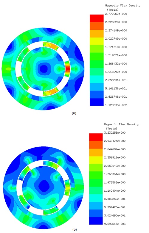
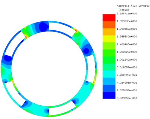
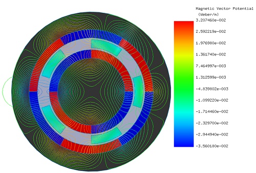
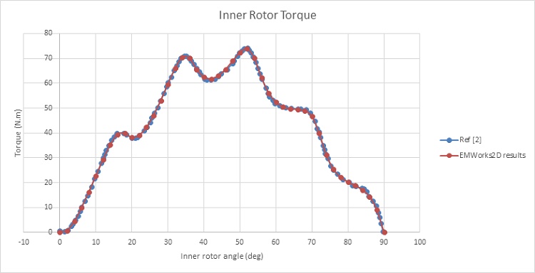
Figure 7 shows the magnetic torque generated on the HS rotor while the LS rotor and the ferromagnetic pieces are kept stationary. The torque is nearly null at $$ \phi_i = 0^\circ $$, then it starts increasing with the angle until reaching a first peak of 70 N.m at $$ \phi_i = 35^\circ $$. The torque curve reaches a second peak of 74 N.m at $$ \phi_i = 51^\circ $$ , then it drops down until becoming again null at $$ \phi_i = 90^\circ $$.
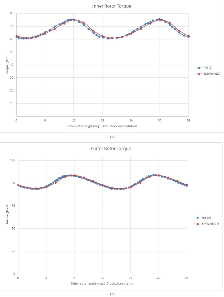
Now the generated torques are evaluated when the inner and outer rotors are both rotating in opposite directions (ferromagnetic pieces are fixed).
The outer rotor angle $$ \phi_o $$ is described using the following equation: $$ \phi_o = - \phi_i \times \frac{p_i}{p_o} $$ [2]. The HS rotor starts at an angle of 40 degrees, resulting in a torque of approximately 62 Nm, while the LS rotor torque is about 98 Nm. Figures 8a) and 8b) illustrate the torques exerted in the inner and outer rotors, respectively. The average torque in the HS rotor is around 67 Nm, compared to nearly 101 Nm in the LS rotor, yielding a gear ratio of approximately 3:2. Consequently, rotating the inner rotor amplifies the torque by 1.5 times in this magnetic gear system.
To address the high ripple torque issue, a new model with increased pole-pairs has been developed and analyzed. The updated magnetic gear structure [2] is depicted in Figure 9, featuring 3 inner rotor pole-pairs (Pi) and 13 outer rotor pole-pairs (Po), resulting in a gear ratio of 4.33. Additionally, the number of ferromagnetic pieces is 16 (Q).
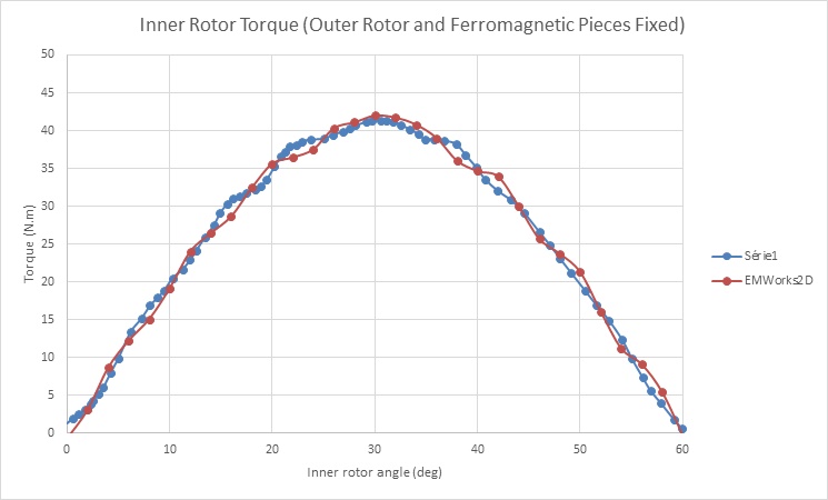
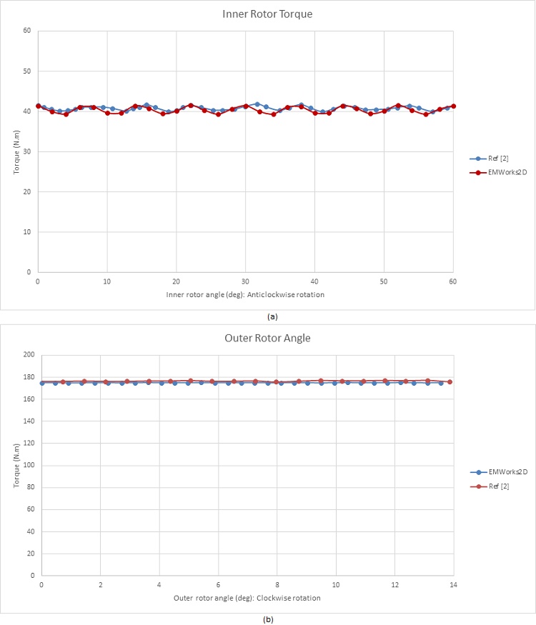
In Figure 10, the flux lines illustrate how the intermediate ferromagnetic pieces conduct the flux within the air gap region. Moving forward, torque calculations are performed with the HS rotor rotating while the LS rotor and ferromagnetic pieces remain fixed (?i varies from 0° to 60°). The resulting torque curve for the HS rotor is depicted in Figure 11, peaking at around 41 N.m at ?i = 30°. Subsequently, Figures 12a) and 12b) display the torque curves for the inner and outer rotors, respectively, spinning in opposite directions. Notably, the HS rotor produces a torque of 41 N.m, while the LS rotor generates approximately 175 N.m. These torque values align with the calculated gear ratio and exhibit reduced ripple effects, particularly evident in Figure 12b) where ripples are nearly eliminated.
Conclusion
The application note focuses on magnetic gears, highlighting their advantages over traditional mechanical gears, including frictionless operation, reduced maintenance, and no direct contact, leading to enhanced efficiency and reliability. Magnetic gears are particularly beneficial in environments requiring clean operation and high safety, such as in electric vehicles and industrial machines. The study uses EMWorks2D to analyze two coaxial magnetic gear models, demonstrating how finite element method (FEM) simulations can optimize torque and magnetic flux distribution. Key findings reveal that magnetic gears can effectively transmit high torque without physical wear, showcasing their potential to revolutionize power transmission systems in various applications. This research underscores the importance of design and simulation in advancing magnetic gear technology for future engineering solutions.
References
[1]:P.M. Tlali, R-J. Wang, S. Gerber. Magnetic Gear Technologies: A Review. IEEE: 2014 International Conference on Electrical Machines (ICEM)
[2]:Thierry Lubin, Smail Mezani, Abderrezak Rezzoug. Analytical Computation of the Magnetic Field Distribution in a Magnetic Gear.
Groupe de Recherche en Electrotechnique et Electronique de Nancy, University Henri Poincaré, Nancy, FRANCE