A Magnetic Gear
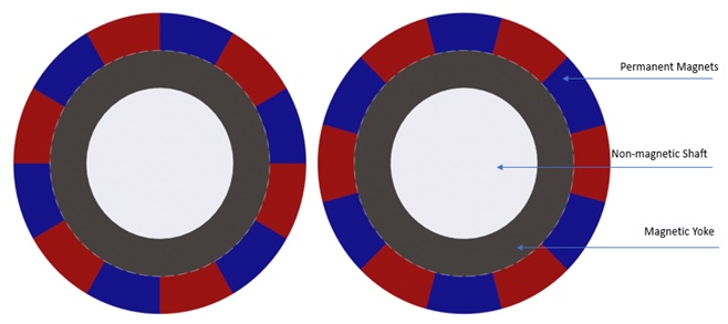
In this note, we explore two magnetic gear systems with parallel axes [1],[2], featuring radial and parallelepiped permanent magnets. Mimicking traditional mechanical gear sets, these systems consist of alternating magnetic poles, a magnetic yoke, and a non-magnetic shaft. The yoke redirects magnetic flux to the magnet poles, driving the magnetic field across the air gap between gear sets and forming closed flux loops between the yoke and permanent magnets.
Example 1 - Radial PM Gear [1]
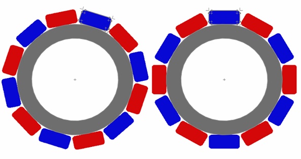
The figure below depicts the magnetic gear system under study, modeled in 2D and analyzed using EMWorks2D. Our investigation will focus on flux and torque variations across different angles and air gap lengths.
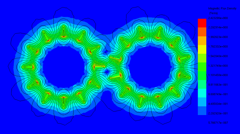
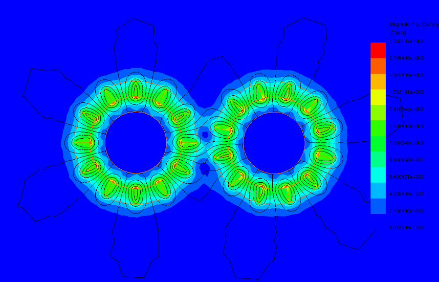
The torque waveform period, calculated as 60 degrees using the formula 360/n (where n is the number of pole pairs), governs the torque transmission in this magnetic gear system. Unlike coaxial systems, torque transfer relies on interactions between adjacent magnets, with maximum torque achieved when the driving gear aligns with half of the magnet arc of the driven gear. Figures 2a), 2b), and 2c) display magnetic flux plots at angles of 0, 15, and 45 degrees, respectively. At 0 degrees, where partial pole overlap occurs, maximum force transmission occurs. Conversely, when poles face each other directly, as depicted in Figures 2b) and 2c), force transmission is minimal.
(a)

(b)
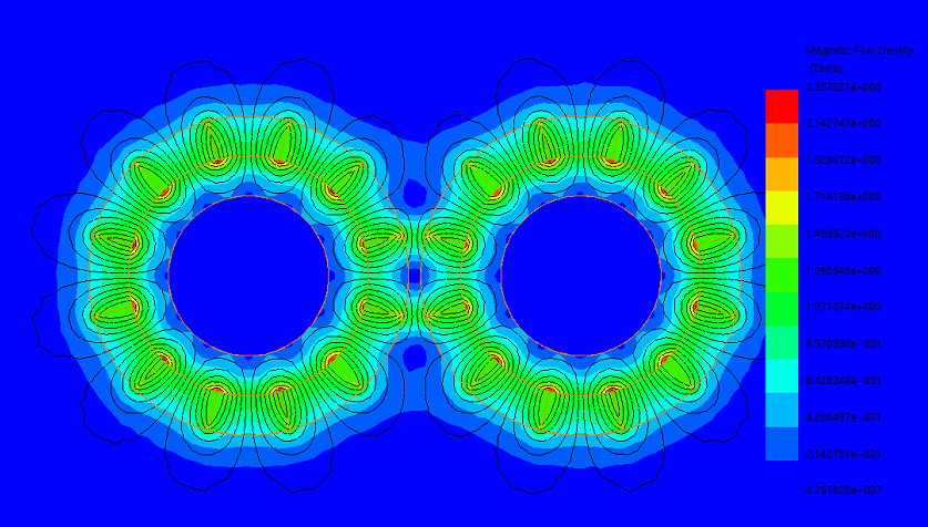
Figure 2 - Magnetic flux density at different positions, a) 0 deg, b) 15 deg, c) 45 deg
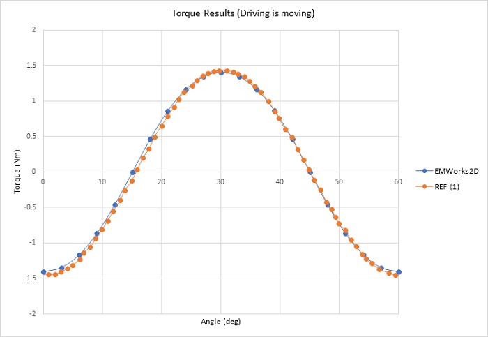
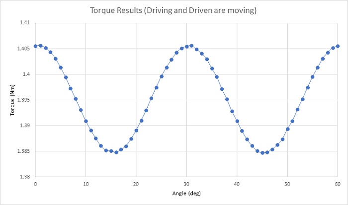
Figure 3 confirms the torque waveform analysis, depicting torque computed as the driving gear rotates while the driven gear remains stationary across one cycle (60 degrees). The torque curve exhibits three peaks of 1.405 Nm at 0, 30, and 60 degrees, with zero crossings at 15 and 45 degrees. Subsequently, both gear sets move in opposite directions. Figure 4 illustrates the resultant torque in both gears, with a gear ratio of 1:1. The torque exhibits minimal ripples, with an average value of 1.395 Nm. Increasing pole pairs can further reduce torque ripples.
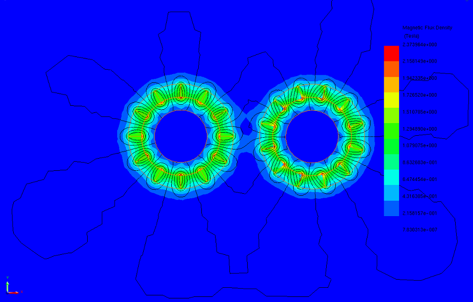
The maximum transferred torque depends on various factors, including the number of pole pairs, magnet thickness, and airgap length. Figures 5a), 5b), and 5c) illustrate magnetic flux density plots at three different airgap lengths, progressively increasing from smaller to larger. In Figure 5a), the field is concentrated in the 0.5mm air gap region, with strong flux continuity between the gear sets. As the air gap increases to 1.5mm (Figure 5b), flux loops decrease, and field intensity diminishes. Figure 5c) shows most flux circulating the poles of the same gear set due to high airgap magnetic reluctance, which increases with airgap length.
(a)
(b)
(c)
Figure 5 - Magnetic flux results at different airgap, a) 0.5 mm, b) 1.5 mm, c) 5 mm
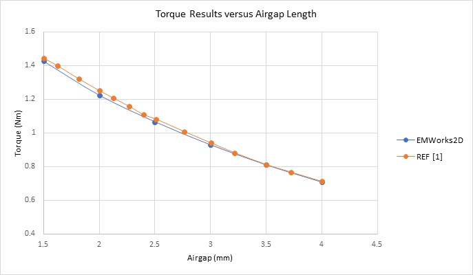
Figure 6 depicts the maximum torque values at varying airgap distances, approximately 1.40Nm at 1.5mm and about 0.7Nm at 4mm.
Example 2: Parallelepiped PM Gear [2]
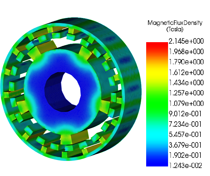
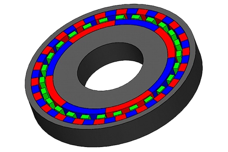
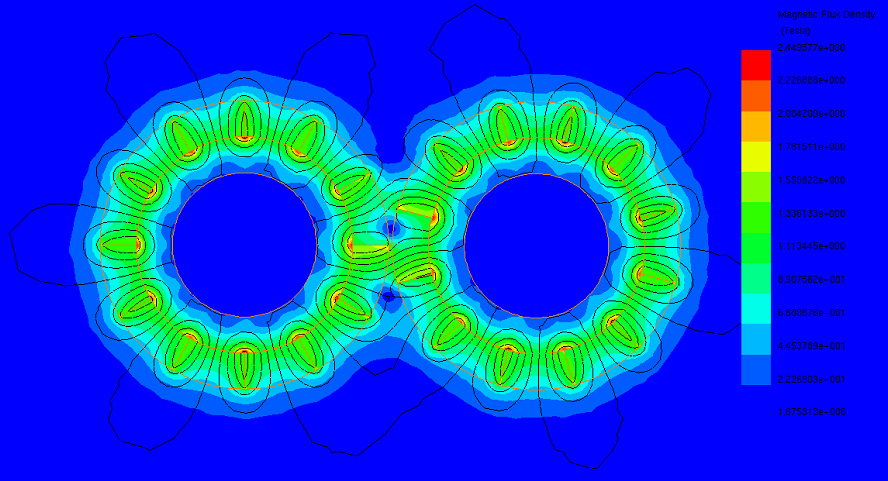
The second simulated example, shown in Figure 7, features a magnetic gear model with parallelepiped magnets. Each gear set consists of 6 Neodymium pole pairs with an iron yoke. The gear poles exhibit radial magnetization due to the small width of the magnets compared to the gear radius.
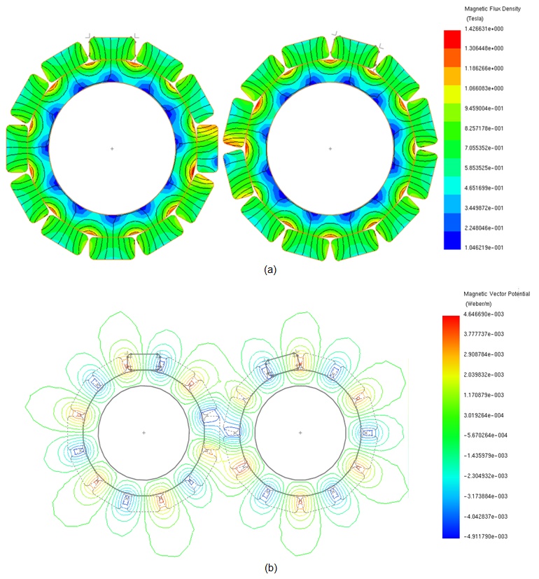
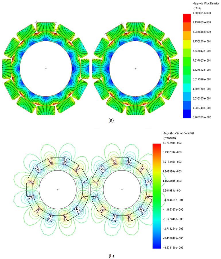
Figures 8a) and 8b) display plots of the magnetic flux density and magnetic vector potential, respectively, corresponding to the maximum transmitted torque position (15 degrees) of the magnetic gear. At aligned pole positions of 0 and 30 degrees, Figures 9a) and 9b) illustrate the magnetic flux and magnetic vector potential plots, respectively. At these positions, where opposite coercivity directions of the gear poles align, the torque is null, similar to when a driving gear pole encounters a fully same-polarity driven gear pole.
The transmitted torque, calculated when one gear set is rotating while the second remains steady, is depicted in Figure 10, peaking at approximately 2.84 Nm at 15 degrees. Figure 11 illustrates the torque plot when both gears are in motion, displaying a sinusoidal pattern with a period of 30 degrees.
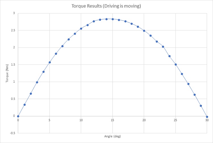
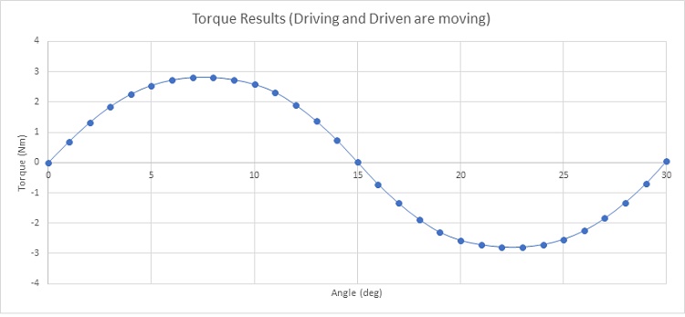
Figure 12 illustrates the torque variation concerning the airgap length for magnetic gear models with 5 and 6 pole pairs. In both configurations, the maximum transmitted torque occurs at the smallest airgap distance, measuring approximately 2.84 Nm and 2.7 Nm for the 5 and 6 pole pairs, respectively. Additionally, it's evident that the magnetic gear with 6 pole pairs generates higher torque compared to the 5 pole pairs configuration.
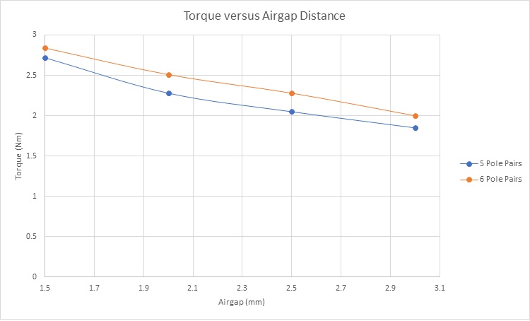
Figure 12 - Torque results versus airgap distance
Conclusion
This application note investigates two magnetic gear systems with parallel axes, utilizing radial and parallelepiped permanent magnets. Through simulations conducted with EMWorks2D, it examines the influence of magnetic flux and torque variations across different angles and air gap lengths. Key findings include the identification of optimal torque transmission moments, which are significantly affected by the alignment of magnetic poles and the size of the air gaps. The study reveals that torque efficiency is maximized when driving and driven gears partially overlap, with torque ripples minimized through an increase in pole pairs. Additionally, the analysis demonstrates that smaller air gaps enhance magnetic flux continuity and torque transmission, establishing a direct correlation between air gap size and gear performance. For parallelepiped magnet gears, the research highlights the importance of magnet alignment and air gap optimization in maximizing torque output. The application note concludes that magnetic gears present a promising alternative to traditional mechanical gears, offering benefits such as reduced wear and potentially longer operational lifespans. This comparative analysis of gear types provides valuable insights for the development and optimization of magnetic gear systems, emphasizing the critical role of magnetic flux management and physical configuration in achieving high-efficiency gear operation.
References
[1]: Yi-Chang Wu and Bo-Syuan Jian. Finite-Element Analysis of the Magnetic Field in a Magnetic Gear. Applied Mechanics and Materials Vols. 479-480 (2014) pp 230-233
Mechanism. 1 Mar. 2015, Applied Mathematics & Information Sciences
[2]: Yi-Chang Wu and Chih-Wen Wang. Transmitted Torque Analysis of a Magnetic Gear Mechanism with Rectangular Magnets. 1 Mar. 2015, Applied Mathematics & Information Sciences