Band-Stop Filters
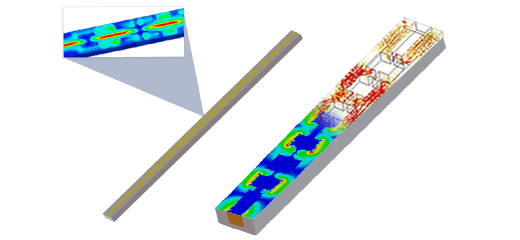
Band-stop filters (BSFs) play a vital role in RF and microwave circuits, effectively suppressing unwanted signals and noise while allowing desired signals to pass through in wireless communication systems. This analysis explores a microstrip line (MSL) BSF design utilizing a quarter-wavelength open-circuited stub, shown in Figure 1. Using HFWorks, an S-parameters study with thermal coupling was conducted to predict its maximum temperature under specific environmental conditions for a given input power.
CAD Model
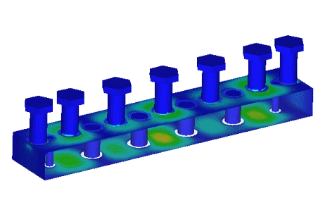
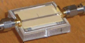
The prototype was crafted using conventional printed board techniques. It features a uniform width strip-line with a 50-? impedance and a quarter-wave open-circuit stub on a Megtron 6 substrate by Panasonic. The Aluminum open metal housing, showcased in Figure 2, is outlined in detail in Table 1 for reference.
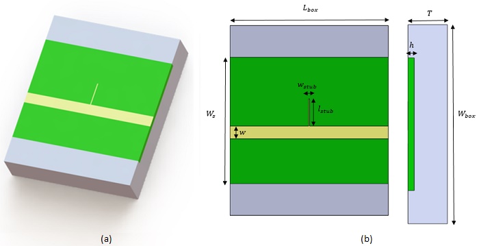
| Geometrical parameter | Dimension (mm) |
| 30 | |
| 25 | |
| 20 | |
| 0.93 | |
| 2 | |
| 4.3 | |
| 0.15 | |
| 5.93 |
Simulation Setup
The S-parameters solver in HFWorks, integrated with thermal analysis, operates effectively across the frequency range of 4GHz to 16GHz. Essential material properties utilized in the simulation are summarized in Table 2.
| Material | Relative permittivity | Dielectric loss tangent | Electrical conductivity (S/m) | Thermal conductivity (W/m.K) |
| Megatron 6 | 3.6 | 0.006 | 0 | 0.4 |
| Aluminum | 1 | 0 | 3.5 E+7 | 237 |
| Copper | 1 | 0 | 5.96E+7 | 401 |
Electromagnetic boundary conditions
Wave port: Ports are defined on the lateral surfaces of both the substrate and the surrounding air box.
PEC (Perfect Electric Conductor): The bottom face of the substrate, representing the ground metal, is modeled as a perfect electric conductor.
IEC (Imperfect Electric Conductor): The microstrip lines, representing the copper conductors, are modeled as imperfect electric conductors.
Thermal boundary conditions
For an excitation power of applied to the input port, a thermal boundary convection is applied to the outer air box at an ambient temperature of 22°C and a convection coefficient set to 9
.
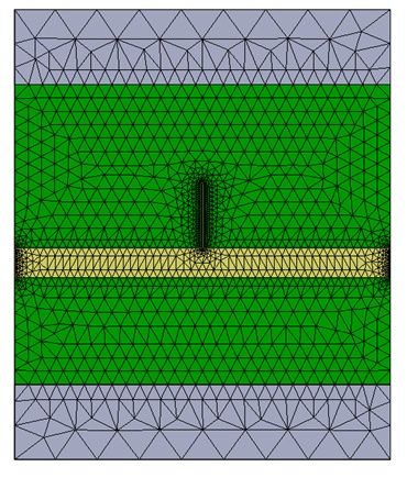
Mesh
To ensure precision in the results, we applied a fine mesh control to both the ports and the open-circuit stub. This optimized meshing strategy enhances the accuracy of our simulations.
Results
A fast sweep S-parameters study conducted over the frequency range of 4 GHz to 16 GHz yielded the following results for a resonant frequency of 10 GHz:
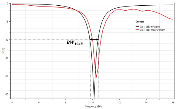
The following figures depict the 2D plot of the S-parameters results: S11 and S21 (Return and insertion losses) for the HFWorks tool and the experimental measurement, plotted against frequency. The deepest rejection is approximately 25 dB at the mid-band frequency of 10 GHz. The achieved 10 dB stopband bandwidth is BW = 5.1%: [9.8 GHz - 10.41 GHz].
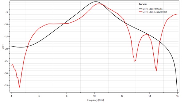
(a) Return loss results
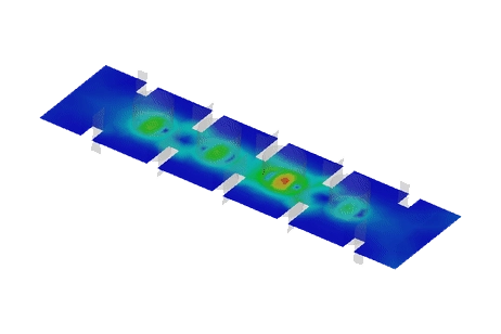
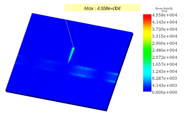
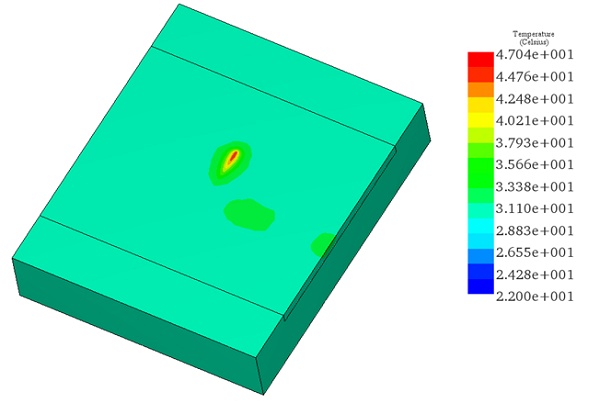
Following the completion of the primary electromagnetic analysis, HFWorks transfers the thermal loads (conductor and dielectric losses) to the thermal solver. With a power excitation of 2W applied to the input port, the simulation yields temperature distribution results across the BSF, considering the applied thermal boundary conditions. The maximum temperature reaches 47°C, aligning well with experimental measurements as documented in Reference [1].
Conclusion
This application note delves into the design and analysis of a band-stop filter (BSF) using a microstrip line with a quarter-wavelength open-circuited stub for RF and microwave circuits. Utilizing HFWorks for an S-parameters study coupled with thermal analysis, the study assesses the filter's performance and thermal behavior under specific input power and environmental conditions. The BSF prototype, constructed on a Megtron 6 substrate with an aluminum housing, aims to suppress unwanted signals within a defined stopband while maintaining low insertion loss outside this range.
The electromagnetic simulation conducted over the frequency range of 4 GHz to 16 GHz identified a resonant frequency at 10 GHz, demonstrating significant signal attenuation of approximately 25 dB within the stopband. Thermal analysis, prompted by a 2W power excitation, revealed a maximum temperature of 47°C across the filter, validating the simulation's accuracy against experimental data.
References
[1]. Sánchez-Soriano, Miguel Á., et al. "Average power handling capability of microstrip passive circuits considering metal housing and environment conditions." IEEE Transactions on Components, Packaging and Manufacturing Technology 4.10 (2014): 1624-1633.