Einführung
Bandsperren (BSFs) sind eine der unverzichtbaren Komponenten für Hochfrequenz- und Mikrowellenanwendungen. Sie werden in drahtlosen HF-Kommunikationssystemen häufig zur wirksamen Unterdrückung von Störsignalen und unerwünschten Breitbandstörungen verwendet, um den Durchgang gewünschter Signale zu ermöglichen. In letzter Zeit sind BSFs zu einem attraktiven Forschungsgebiet für Wissenschaftler geworden, da sie sowohl in Empfängern als auch in Sendern verwendet werden können und in nichtlineare Schaltungen wie Mischer, Oszillator und Verstärker integriert wurden, um deren Leistung zu verbessern.
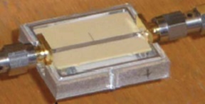
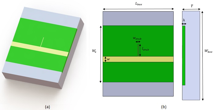
Das in dieser Analyse untersuchte HF-Gerät besteht aus einem Mikrostreifenleitungs-Bandsperrfilter (MSL-Bandsperrfilter, BSF) unter Verwendung einer Viertelwellenlängen-Stichleitung mit offener Schaltung. Abbildung 1 zeigt den funktionierenden Prototyp der vorgeschlagenen Implementierung für die Schmalband-BSF erster Ordnung mit einem offenen Metallgehäuse.
Um die maximal erreichte Temperatur für eine bestimmte Eingangsleistung unter genau definierten Umgebungsbedingungen vorherzusagen, wurde eine S-Parameter-Studie mit thermischer Kopplung des HFWorks-Werkzeugs verwendet.
Problembeschreibung
Der funktionierende Prototyp wurde durch eine Standard-Leiterplattenherstellungstechnik realisiert. Die Schaltung besteht aus einer gleichbreiten Streifenleitung einer 50 Impedanz mit einer zentralen Viertelwellen-Leerlauf-Stichleitung. Es ist auf einem Megtron 6-Substrat (von Panasonic) und einem offenen Metallgehäuse aus Aluminium (siehe Abbildung 2) implementiert. Die geometrischen Abmessungen sind in Tabelle 1 aufgeführt.
| Geometrischer Parameter | Abmessung (mm) |
| | 30 |
| 25 | |
| | 20 |
| 0,93 | |
| | 2 |
| 4.3 | |
| 0,15 | |
| | 5,93 |
Simulations-Setup
Der S-Parameter-Löser von HFWorks wird in Verbindung mit dem thermischen Gehäuse für einen Arbeitsfrequenzbereich von [4 GHz-16 GHz] verwendet. Die Eigenschaften der verwendeten Materialien sind in Tabelle 2 zusammengefasst.
| Material | Relative Dielektrizitätskonstante | Tangens des dielektrischen Verlusts | Elektrische Leitfähigkeit (S/m) | Wärmeleitfähigkeit (W/mK) |
| Megtron 6 | 3.6 | 0,006 | 0 | 0,4 |
| Aluminium | 1 | 0 | 3,5 E + 7 | 237 |
| Kupfer | 1 | 0 | 5,96E + 7 | 401 |
Elektromagnetische Randbedingungen
1- Wave-Port: Die Ports werden auf die Seitenflächen des Substrats und die entsprechenden Seitenflächen der Airbox aufgebracht.2- PEC: Die Unterseite des Substrats (Grundmetall) soll ein perfekter elektrischer Leiter sein.
3- IEC: Die Mikrostreifenleitungen (Kupferleiter) sollten ein nicht perfekter elektrischer Leiter sein.
Thermische Randbedingungen
Für eine Anregungskraft vonGittergewebe
Um die Genauigkeit der erhaltenen Ergebnisse zu verbessern, wurde eine Feinmaschenkontrolle auf die beiden Anschlüsse und den Leerlaufstutzen angewendet, wie in der nächsten Abbildung des vermaschten Modells gezeigt.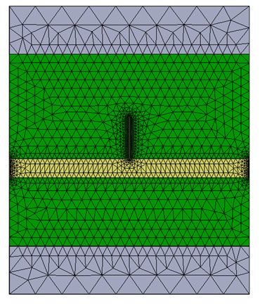
Ergebnisse
Eine Fast-Sweep-S-Parameter-Studie für den Frequenzbereich von [4GHz-16GHz] ergab die nächsten Ergebnisse für eine Resonanzfrequenz von 10GHz:
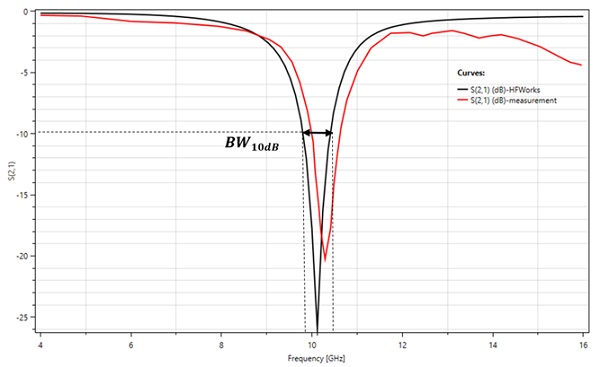
Die folgenden Abbildungen zeigen die 2D-Darstellung der Ergebnisse der S-Parameter: S11 und S21 (Rückführungs- und Einfügungsverluste) für das HFWorks-Werkzeug und die experimentelle Messung in Abhängigkeit von der Frequenz. Die tiefste Unterdrückung beträgt etwa 25 dB bei einer Mittenfrequenz von 10 GHz. Die erhaltene 10-dB-Stopband-Bandbreite =5,1%: [9,8 GHz-10,41 GHz].
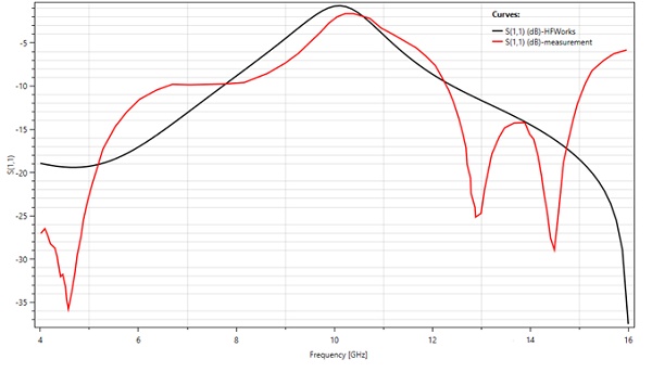
(a) Renditeverlustergebnisse
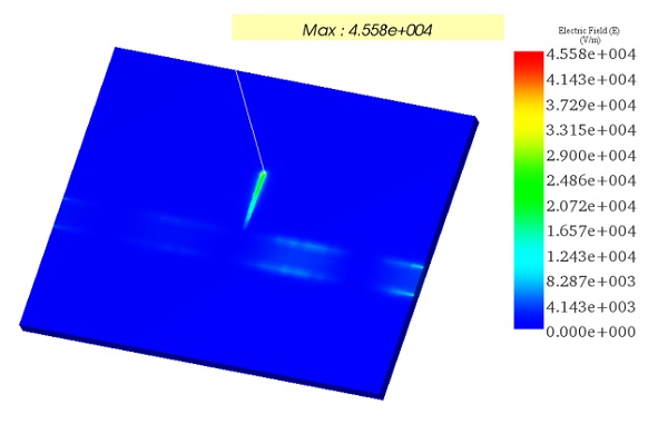
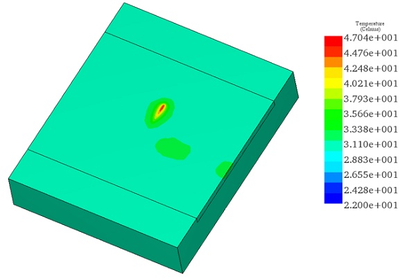
Nach der Lösung der elektromagnetischen Hauptstudie leitet HFWorks die thermischen Lasten (Leiter- und dielektrische Verluste) an den thermischen Solver weiter. Unter einer Leistungsanregung von 2 W, die an den Eingangsanschluss angelegt wurde, ergab die Simulation die nächsten Ergebnisse der Temperaturverteilung über die BSF unter Berücksichtigung der angewendeten thermischen Randbedingungen. Die Temperatur erreicht einen Maximalwert von 47 ° C, was gut mit der experimentellen Messung gemäß der Literaturstelle [1] übereinstimmt.
Fazit
Unter Verwendung von HFWorks wurde eine elektrothermische Analyse eines offenen Bandstopp-Filters untersucht. Die Analyse ermöglichte es, vorherzusagen, wie heiß das HF-Gerät unter einer festgelegten niedrigen Erregerleistung, unter Berücksichtigung der äußeren Randbedingungen und unter Verwendung eines äußeren Metallgehäuses werden kann. Die maximale Belastbarkeit des Microstrip-Schaltkreises wurde anhand seines Erwärmungsprozesses (der durch seine ohmschen und dielektrischen Verluste erzeugt wird) analysiert.Die gute Übereinstimmung zwischen den Simulations- und Messergebnissen zeigt, wie sehr sich Wissenschaftler bei HF-Anwendungen auf die Berechnung der Wärmeabschätzung von HFWorks verlassen konnten.