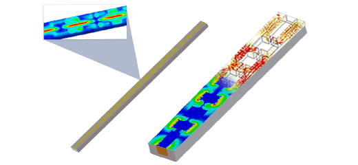
RLC Bandpass Filter
An RLC circuit combines resistors, inductors, and capacitors, finding applications in oscillators, radio and TV tuners, filters, and more. These circuits are typically second-order, described by second-order differential equations. However, inductor resistance can impact performance. HFWorks allows the simulation of RLC circuits, using lumped elements or modeling actual coils. This tutorial focuses on a lumped-element RLC filter, integrating circuit and 3D models in a single study, operating at 1 GHz with a 10% bandwidth.
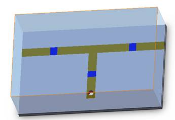
Figure 1 - 3D view of an RLC filter
Simulation
To simulate this filter's behavior, we'll perform a Scattering Parameters study, focusing on the desired frequency band (21 frequencies from 1.8 GHz to 3.8 GHz). HFWorks offers various plot options for customized output results.
Solids and Materials
In this simulation, the microstrip lines consist of perfect electric conductors on a Mat1 substrate. The RLC components are modeled on three shields with the following values: 127 nH and 0.2 pF for the shields close to the ports, and 0.726 nH and 34.9 pF for the parallel shield, implemented as a parallel RLC circuit..
Load/ Restraint
The ports in the simulation are applied to the lateral faces of the substrate, including the sides of the horizontal microstrip line with the two RLC shields, as well as the air box. This approach allows the simulation to consider the electric field's distribution in the air and ensures that the radiation boundaries provide results that are more in line with the quasi-TEM theory of wave transmission over a microstrip line
Meshing
Given that the signal's path involves both the ports and the input signal surfaces, it's important to concentrate the mesh on these specific areas. This focused meshing approach assists the solver in refining its precision on the eddy currents and takes into account the shape of the signal path.
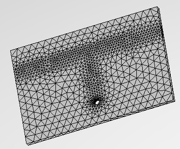
Figure 2 - Mesh of the dipole antenna
Results
There are various 3D and 2D plots available, depending on the specific parameters of interest. In the context of this filter simulation, it is essential to plot the insertion and return losses. The following figure illustrates both the insertion and return losses of the filter under consideration:
.jpg)
Figure 3 - Insertion and return loss of the filter around 1 GHz
The insertion loss remains remarkably low within the frequency band around 1 GHz, providing excellent isolation below 0.94 GHz and above 1.06 GHz. When dealing with matching issues, plotting the return loss on a Smith chart is more relevant. In this context, the following figure presents the S11 curve, with a red marker indicating the return loss at 1 GHz:
.jpg)
Figure 4 - Variations of reflection coefficient at the filter's port
The electric field distribution at 1 GHz is depicted in the following figure. It is evident that the electromagnetic wave effectively propagates through the circuit and reaches the second port:
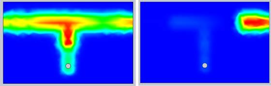
Figure 5 - Electric field vector distribution on the circuit at the aimed frequency (1 GHz and 0.83 GHz)
Conclusion
The RLC bandpass filter, a fundamental component in various electronic applications, integrates resistors, inductors, and capacitors to achieve desired frequency responses. Using HFWorks, simulations of such filters, either with lumped elements or actual coil models, provide insights into their behavior. This tutorial focused on a lumped-element RLC filter operating at 1 GHz with a 10% bandwidth. Through a Scattering Parameters study, the filter's performance was analyzed, emphasizing insertion and return losses. The simulation highlighted low insertion loss within the desired frequency band and effective isolation at nearby frequencies. Additionally, the electric field distribution illustrated efficient wave propagation through the circuit. These findings underscore the importance of accurate modeling and simulation tools in optimizing RLC filter designs for specific frequency requirements and performance criteria.