A T-Shaped Electromagnetic Actuator
This article discusses the outcomes of a 3D FEM simulation on a T-shaped electromagnetic actuator, crucial for efficient actuator design. Utilizing EMS software, the study examines magnetic parameters such as flux, force, and speed. Results, compared with experimental data, analyze the coil's force relative to ampere-turns and air gap distance. Additionally, motion analysis, coupled with EMS, computes linear displacement and velocity.
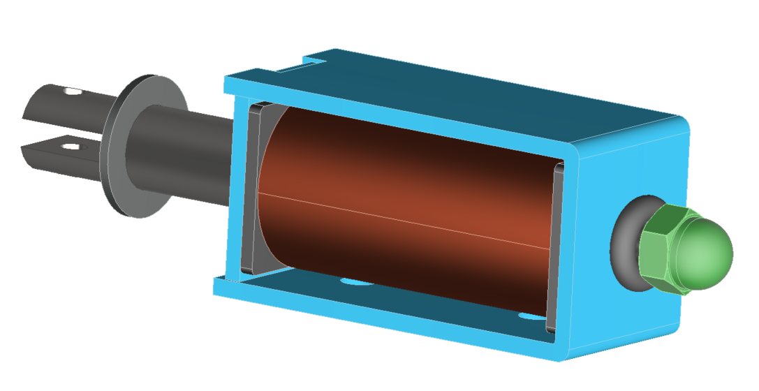
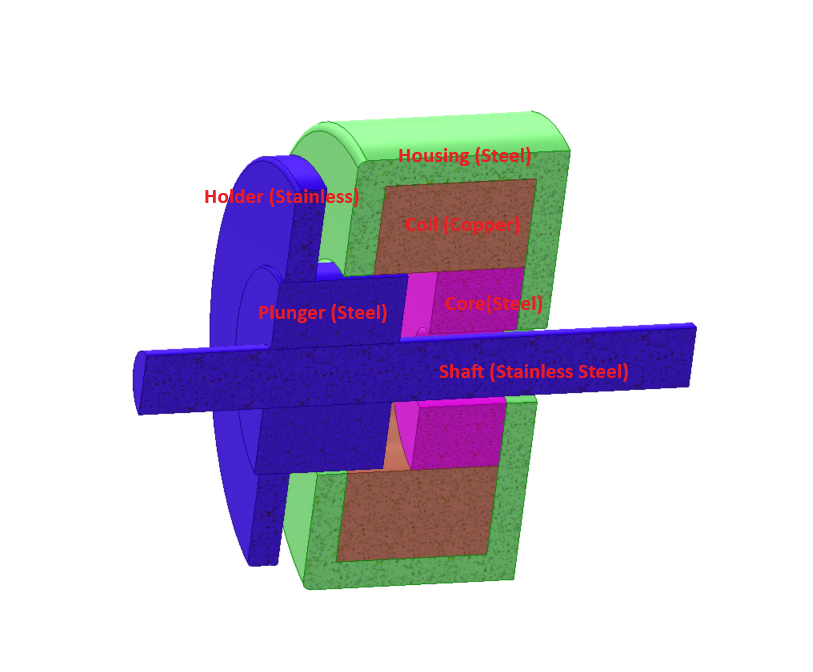
Figure 1 depicts the actuator's geometry, while Table 1 lists its main dimensions [1]. Figure 2 illustrates the 3D model.
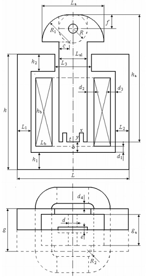
| h | 52.5 | g | 19.8 | f | 6.30 | hb | 31.2 |
| h1 | 7.90 | ha | 57.8 | R | 6.50 | Lb | 7.50 |
| h2 | 7.90 | La | 28.3 | R1 | 12.30 | d1 | 2.40 |
| L | 50.90 | La1 | 13.0 | ga | 14.30 | d2 | 3.00 |
| L1 | 6.35 | c | 4.65 | x | 1.60 | d3 | 2.10 |
| L2 | 6.35 | d | 4.00 | y | 4.20 | d4 | 2.25 |
| L3 | 16.5 | e | 2.60 | t | 6.00 | R2 | 2.40 |
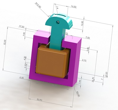
Figure 1 - 3D model of the electromagnet structure
3D EM simulation
Parametric Analysis conducted through EMSEM simulation enables comprehensive exploration of various electromagnet aspects across multiple scenarios. EMS facilitates the simultaneous evaluation of numerous cases by parameterizing simulation and geometric variables. Utilizing EMS's Magnetostatic study type, magnetic results like flux density, field intensity, force, and torque are computed and visualized. This study focuses on determining the magnetic force generated by the actuator concerning both air gap distance and ampere-turns.
Simulation Setup: The analysis begins with the creation of a parameterized Magnetostatic analysis, with ampere-turns and air gap distance as the parametric variables. Table 2 outlines the simulated scenarios.
Table 2 - Simulation scenarios
| Scenarios | Air gap length (mm) | Ampere-turns (A-t) |
| scenario 1 | 2 | 575 |
| scenario 2 | 3 | 575 |
| scenario 3 | 4 | 575 |
| scenario 4 | 5 | 575 |
| scenario 5 | 6 | 575 |
| scenario 6 | 7 | 575 |
| scenario 7 | 2 | 460 |
| scenario 8 | 3 | 460 |
| scenario 9 | 4 | 460 |
| scenario 10 | 5 | 460 |
| scenario 11 | 6 | 460 |
| scenario 12 | 7 | 460 |
| scenario 13 | 2 | 345 |
| scenario 14 | 3 | 345 |
| scenario 15 | 4 | 345 |
| scenario 16 | 5 | 345 |
| scenario 17 | 6 | 345 |
| scenario 18 | 7 | 345 |
2. The ferromagnetic parts are made of non-oriented steel. Figure 3 contains the BH curve of the used steel. The coil is made of copper.
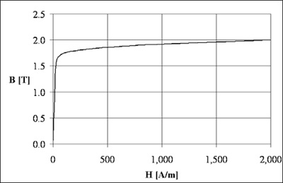
Figure 3 - B-H curve [1]
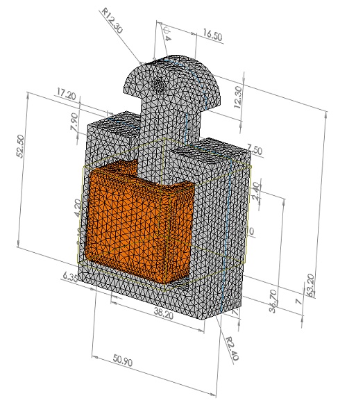
3. Figure below shows the meshed model. It is possible to define specific mesh element sizes on selected surfaces or bodies.
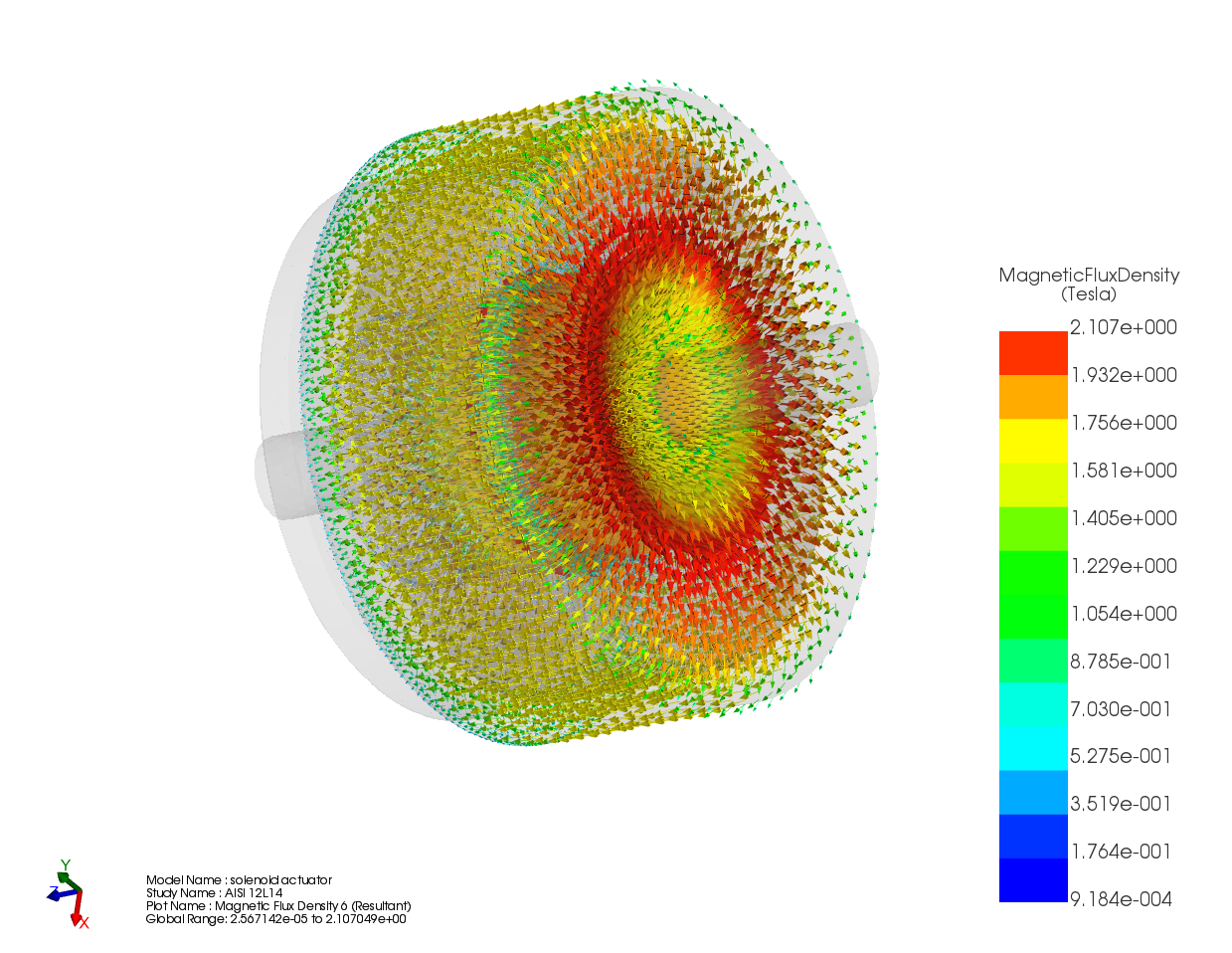
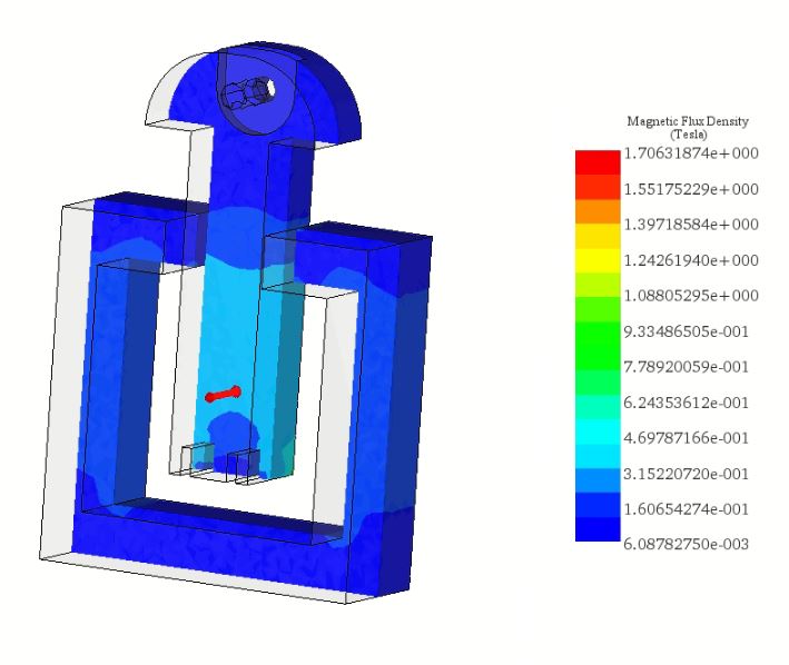
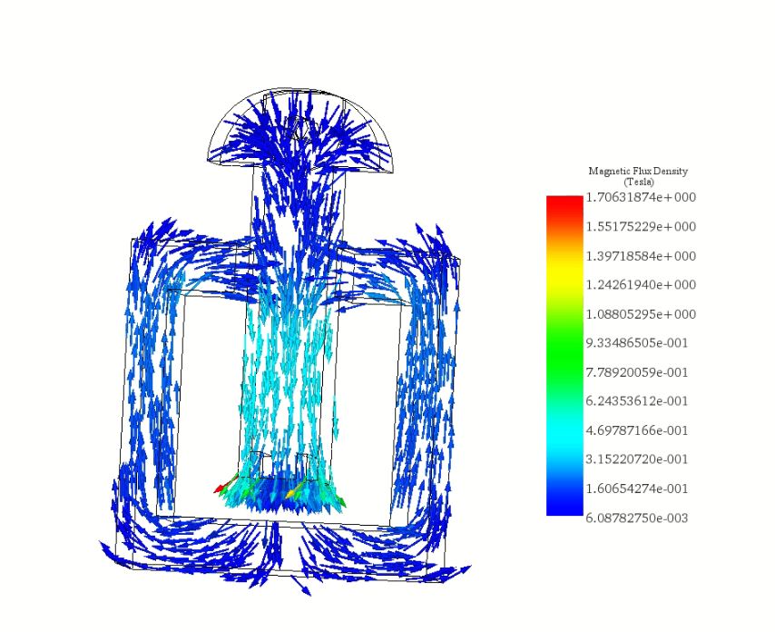
For the scenario with 460 A-t and a 6 mm air gap, Figure 5 illustrates the magnetic flux density, predominantly following the steel path with high permeability. Meanwhile, Figure 6 depicts a vector plot of magnetic flux density at 575 A-t.
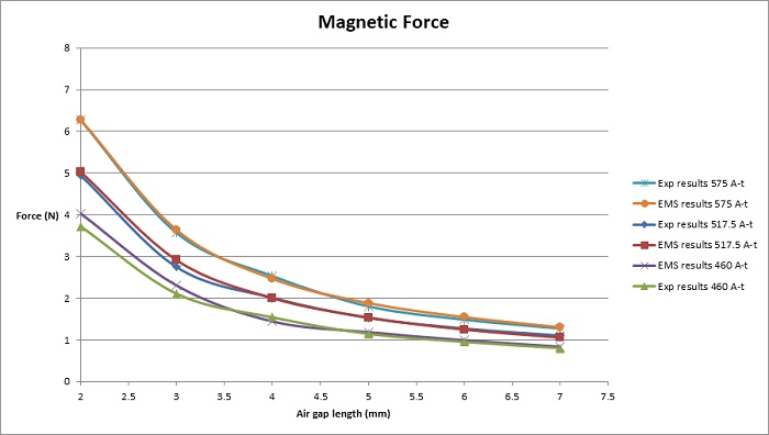
Comparing the magnetic force computed via EMS to experimental measurements [1] (shown in Figure 7), it's evident that force, directly proportional to coil ampere-turns, increases from approximately 4 N at 460 A-t to about 6.3 N at 575 A-t. Notably, force amplifies with reduced air gap distance, as larger gaps lead to higher magnetic reluctance, resulting in diminished flux and force.
Examining the force curves reveals maximal values at 2 mm and minimal values at 7 mm air gap length for each curve. Specifically, the highest force is observed at 575 A-t and a 2 mm air gap length, as depicted in Figure 7.
Motion Simulation
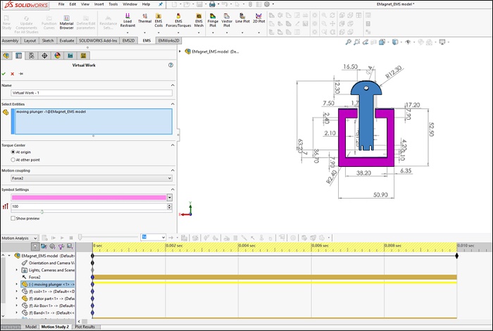
EMS offers the ability to integrate electromagnetic fields with motion through coupling. The electromagnetic force computed by EMS is utilized by SW Motion's solver to generate mechanical motion. Figure 8 illustrates the motion study settings.
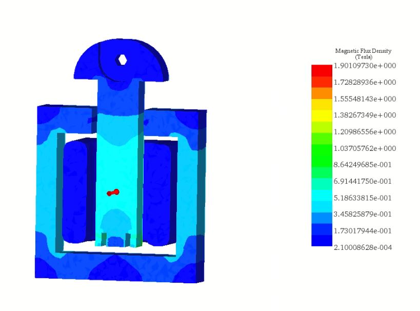
In Figure 9, a cross-sectional view showcases the magnetic flux density plot within the moving plunger and the core at 0.025s (AT=575 A-t). Initially, at t=0s, the plunger's position is Y=0 mm, with an air gap distance of 7 mm.
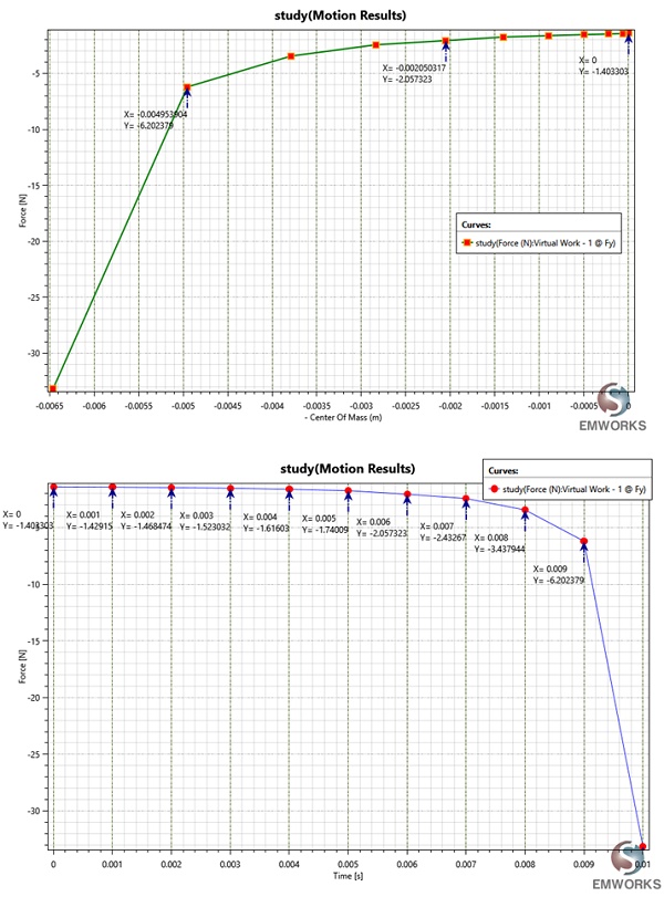
Figures 10a) and 10b) depict the magnetic force computed by EMS acting on the moving part and incorporated into the SW motion analysis, respectively, plotted against position and time. At 0 mm, the force measures F=1.4N, increasing to approximately F=6.20N at Y= -0.0049m (refer to Figure 10a). These findings closely align with those presented in Figure 7 (575 A-t). Notably, the force on the plunger reaches 33.16N at 0.01s (see Figure 10b).
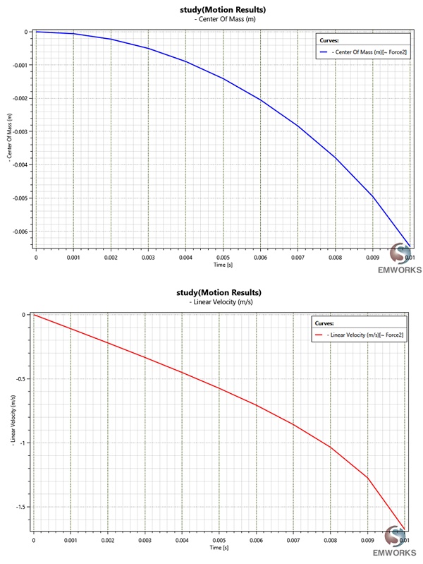
In Figures 11a) and 11b), the plunger's position over time and the instantaneous linear velocity are depicted, respectively. At 0.01s, the velocity peaks at 1.67 m/s, correlating with the force's influence on velocity.
Conclusion
The application note delves into the comprehensive 3D FEM simulation of a T-shaped electromagnetic actuator, highlighting its performance in generating magnetic force, and flux density and enabling precise motion control. Utilizing EMS software, the study scrutinizes the actuator's magnetic parameters through parametric analysis, considering variables like ampere-turns and air gap distances. The simulations demonstrate a direct relationship between coil ampere-turns and the magnetic force exerted, with force increasing alongside ampere-turns and decreasing air gap distances. This relationship underscores the actuator's efficiency in converting electromagnetic force into mechanical motion, as evidenced by motion simulations that reveal the actuator's dynamic response under varying electromagnetic conditions.
The findings, corroborated by experimental data, confirm the simulation's accuracy in predicting the actuator's behavior, showcasing the potential of EMS software in optimizing electromagnetic actuator designs. The integration of electromagnetic fields with motion analysis further exemplifies the actuator's capability to achieve targeted linear displacement and velocity, essential for precision applications.
References
[1]: Alin-Iulian DOLAN, Ivan YATCHEV and Krastio HINOV . COMPARISON OF DIFFERENT FORMULATIONS AND TECHNIQUES
FOR 3D STATIC FORCE COMPUTATION OF A T-SHAPED ELECTROMAGNET.