An Electromagnetic Clutch
The clutch (Figure 1) is vital in an automobile's transmission system, smoothly transferring power from the engine to the gearbox without shock. It temporarily disconnects the engine from the gearbox, essential for gear shifts to prevent gear teeth damage. Thus, the clutch is critical for starting, shifting gears, and idling.
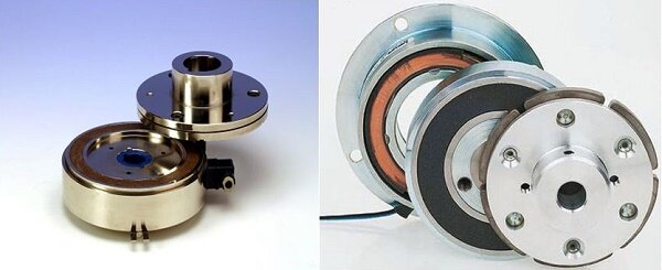
Figure 1 - Electromagnetic Clutch
The EM clutch, shown in Figure 2, consists of a coil shell, armature, rotor, and hub, with a friction-coated armature plate. When activated, the coil generates a magnetic field, magnetizing the rotor and drawing the armature to it, thus transferring torque through frictional force. Engagement time varies with magnetic field strength, inertia, and air gap. Deactivation occurs when voltage is cut, with a spring mechanism resetting the armature and air gap.
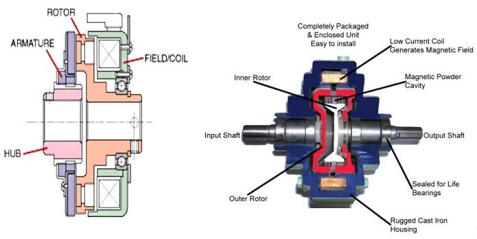
Figure 2 - Components of electromagnetic clutch
EM clutches facilitate remote activation without mechanical linkage, making them suitable for printing machines, conveyor systems, copiers, and factory automation. In automobiles, they replace the clutch pedal with a switch button and are also used in air conditioning compressors, demonstrating their versatility and efficiency in diverse applications.
Model Setup
This example demonstrates a dynamic interaction where an excited coil induces an electromagnetic force, pulling the armature towards the rotor. Integrating SW Motion with EMS's Magnetostatic Study, it sets up a motion study where the two solvers exchange data on force and plunger position iteratively. EMS calculates the initial force, SW Motion updates the plunger's position based on this force, and then EMS recalculates the force for the new position. This back-and-forth communication continues throughout the simulation, ensuring accurate modeling of the electromagnetic phenomenon.
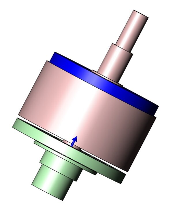
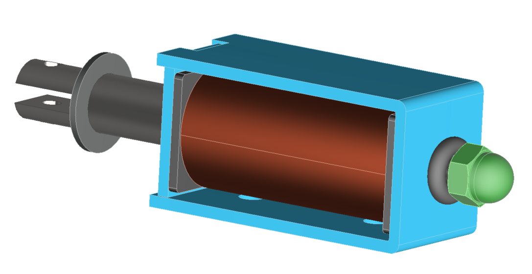
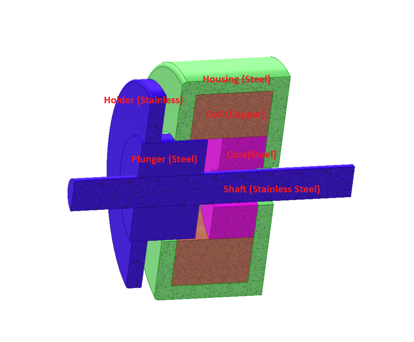
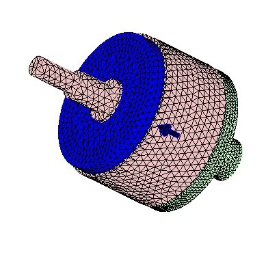
Figure 3 - 3D model of the clutch
The Study
The integration of EMS's Magnetostatic module enables the calculation and visualization of flux density and armature motion. To conduct a comprehensive analysis, the following four critical steps are essential: 1) Assign appropriate materials to all solid bodies; 2) Implement the necessary boundary conditions, also known as Loads/Restraints in EMS; 3) Mesh the entire model; 4) Execute the solver. Adhering to these steps ensures accurate and efficient simulation outcomes.
Materials
In the Magnetostatic analysis conducted with EMS, the crucial material property needed is the relative permeability, as detailed in Table 1.
Table 1 - Table of materials
| Components / Bodies | Material | Relative permeability |
| Coil | Copper | 0.999991 |
| Shell Coil | AISI 1010 Steel | Nonlinear |
| Inner Air | Air | 1 |
| Band | Air | 1 |
| Armature | AISI 1010 Steel | Nonlinear |
| Hub | Steel 1018 | Nonlinear |
| Air Cylinder | Air | 1 |
| Rotor | AISI 1010 Steel | Nonlinear |
| Shaft | Steel 1018 | Nonlinear |
The EMS Materials library encompasses a comprehensive collection of material properties and provides users the flexibility to add any additional materials as required.
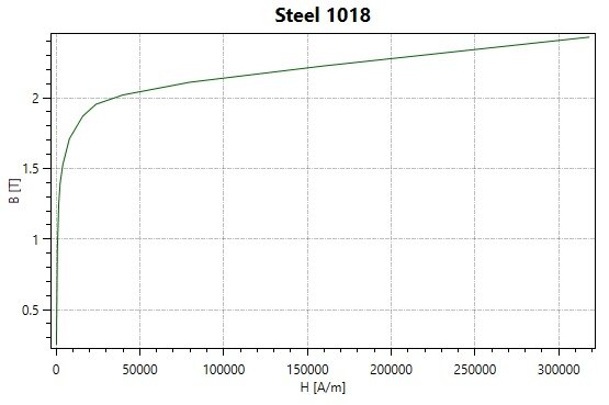
Figure 4 - BH curve of Steel 1018
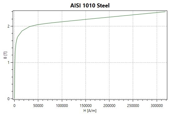
Figure 5 - BH curve of AISI 1010 Steel
Coil and Force information
In this study, a coil is utilized, as specified in Table 2.
Table 2 - Coils information
| Name | Number of turns | Magnitude |
| Wound Coil 1 | 1015 | 0.73101 A |
Meshing
Meshing is crucial in EMS design analysis, with element size tailored to the model’s geometric complexity for optimal accuracy and efficiency. Initial designs may use larger elements for speed, while detailed analyses require finer meshing for precision. Air regions are split into inner and outer zones, allowing dense meshing where fields are strong and coarser meshing where they decay, balancing detail and computational load. For motion studies, a "Band" component facilitates the re-meshing of moving parts, ensuring accurate simulation results throughout the analysis.
Results
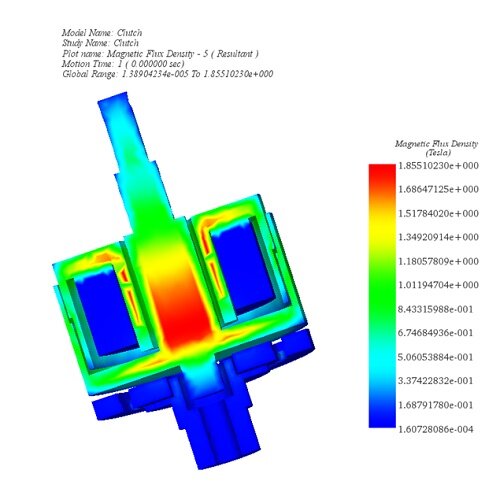
Figure 7 - Magnetic Flux density, section view (Step 1)
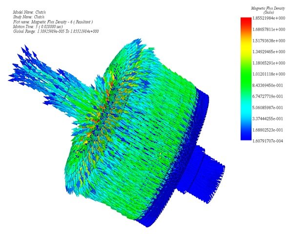
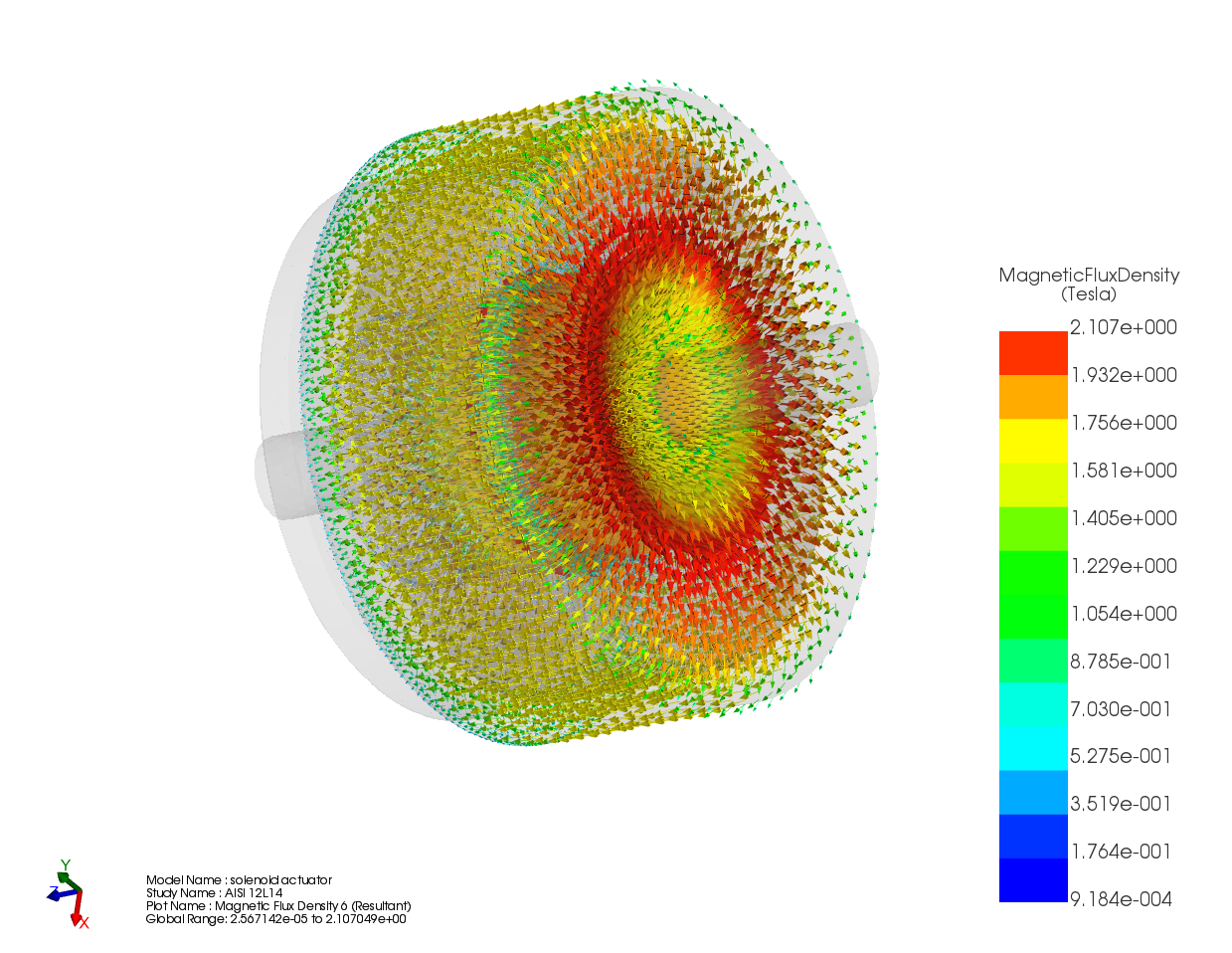
Figure 8 - Magnetic Flux Density, vector plot (Step 3)
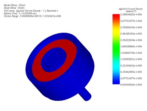
Figure 9 - Applied Current Density, section view (Step 3)
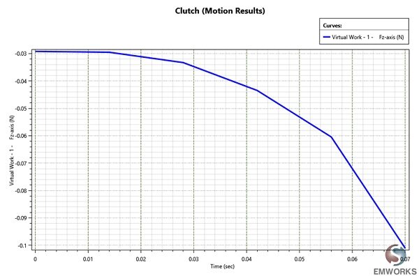
Figure 10 - Force generated by the coil
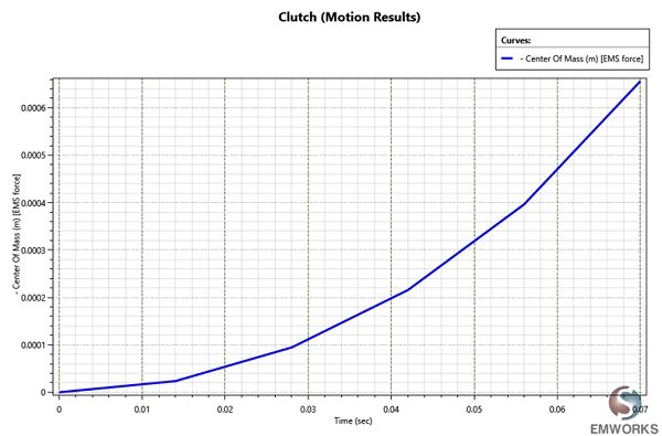
Figure 11 - Displacement of the armature versus time
Conclusion
The electromagnetic (EM) clutch, pivotal in automotive transmission systems for smooth power transfer and gear shifting, exemplifies innovation in electromechanical design. Utilizing a coil to generate a magnetic field, it magnetizes the rotor, engaging the armature through frictional force, thus enabling torque transfer. This mechanism allows for rapid engagement and disengagement, contingent on magnetic field strength, inertia, and the air gap, with a spring mechanism facilitating deactivation. The integration of EM clutches in various applications, from vehicles to industrial machinery, underscores their versatility and efficiency, particularly in enabling remote activation without mechanical linkage. This application note detailed a dynamic simulation using EMS's Magnetostatic Study, demonstrating the intricate interplay between electromagnetic forces and mechanical motion. Through rigorous methodology—material assignment, boundary condition application, meshing, and solver execution—the study showcased the clutch's operational dynamics, offering insights into flux density, armature motion, and force generation. This detailed analysis not only validates the EM clutch's effectiveness but also highlights its potential to enhance operational efficiency across diverse mechanical applications.