Linear Solenoid
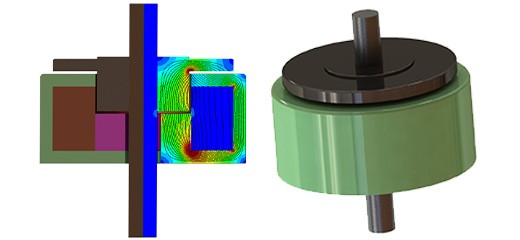
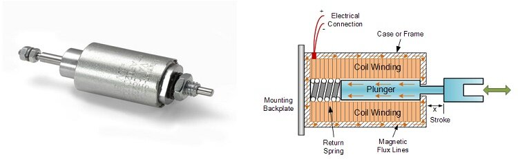
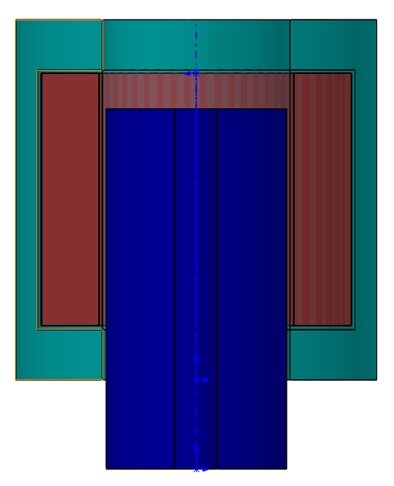
A "Linear Solenoid" is an electromagnetic device that converts electrical energy into mechanical motion. It consists of an electrical coil wound around a cylindrical tube with a Ferro-magnetic actuator or "plunger" that moves in response to the coil's energization. Solenoids are versatile and find applications in various fields, such as opening doors, closing valves, operating robotic mechanisms, and actuating electrical switches.
When an electrical current flows through the coil, it creates a magnetic field that attracts the plunger towards the center of the coil. This movement is controlled by adjusting the current or the coil's characteristics.
Description of the problem
In this example, we simulate a scenario where a coil is excited, inducing an electromagnetic force that translates the plunger. This phenomenon is modeled using a motion study, coupled with the Magnetostatic Study of EMS.
The EMS solver and the motion solver collaborate throughout the simulation. EMS calculates the force at the initial position, sends the force value to SW Motion, which then applies it to the plunger, calculates the new position, and sends it back to EMS. This iterative process continues until all steps are covered, with both solvers exchanging information about the force and location of the plunger.
Study
When using the Magnetostatic module of EMS in conjunction with Motion, it is essential to follow four key steps:
-
Apply the appropriate material properties to all solid bodies in the model.
-
Implement the necessary boundary conditions, also known as Loads/Restraints in EMS.
-
Create a mesh for the entire model to discretize it effectively.
-
Run the solver to compute and visualize the flux density and motion of the plunger. These steps are crucial for accurate simulation results.
Materials
In the Magnetostatic analysis of EMS, one of the essential material properties to specify is the relative permeability, which can be found in Table 1 of the simulation setup. This property is crucial for accurately modeling electromagnetic behavior within the system.
Table 1 - Table of materials
| Components / Bodies | Material | Relative permeability |
| Coil | Copper | 0.999991 |
| Outer Air | Air | 1 |
| Inner Air | Air | 1 |
| Band | Air | 1 |
| Plunger | Mild Steel | 2000 |
| Stator | Mild Steel | 2000 |
Loads and Restraints
In this study, loads and restraints play a vital role in defining the electric and magnetic environment of the model. The accuracy and reliability of the analysis results directly hinge on the proper specification of these loads and restraints. They are applied to specific geometric entities and remain fully associative with the geometry, adjusting automatically to any geometric changes.
For instance, in this analysis, a coil (as specified in Table 2) is applied as part of the loads and restraints configuration to accurately simulate the electromagnetic behavior of the system.
Table 2 - Coils information
| Name | Number of turns | Magnitude |
| Wound Coil 1 | 50 | 0.8 A |
The plunger's behavior is crucial for understanding the virtual work in this analysis, as detailed in Table 3.
| Name | Torque Center | Components / Bodies |
| Virtual Work | At origin | Plunger |
Meshing
Meshing is a critical design analysis step in EMS. The mesh size is determined based on various factors like model volume, surface area, and geometry. You can choose a larger element size for quicker results in preliminary design stages. For accuracy, smaller elements may be needed.
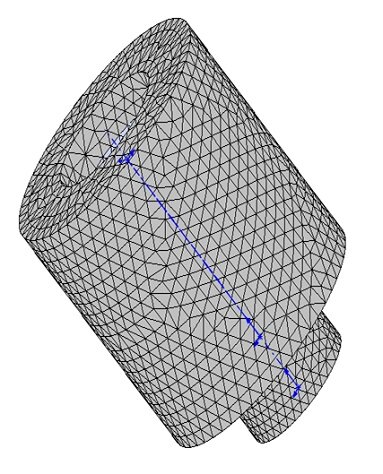
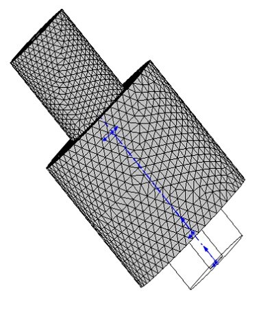
To optimize meshing, we divide the air region into inner and outer parts. This approach is recommended as it allows denser meshing where the field is significant and coarser meshing where the field is weaker, saving computational resources.
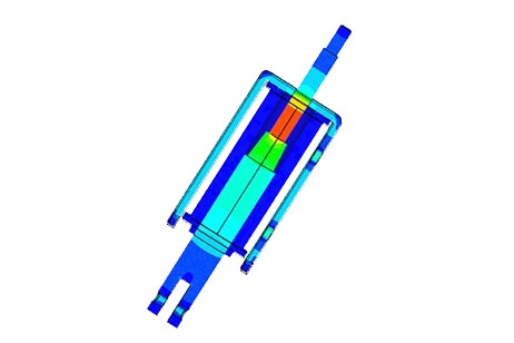
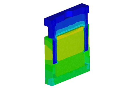
In motion-coupled studies, we use a component called "Band" around moving parts. This enables re-meshing of both the moving parts and the Band in each simulation step. Figures 3 and 4 depict the mesh in step 1 and step 11, respectively.
Results
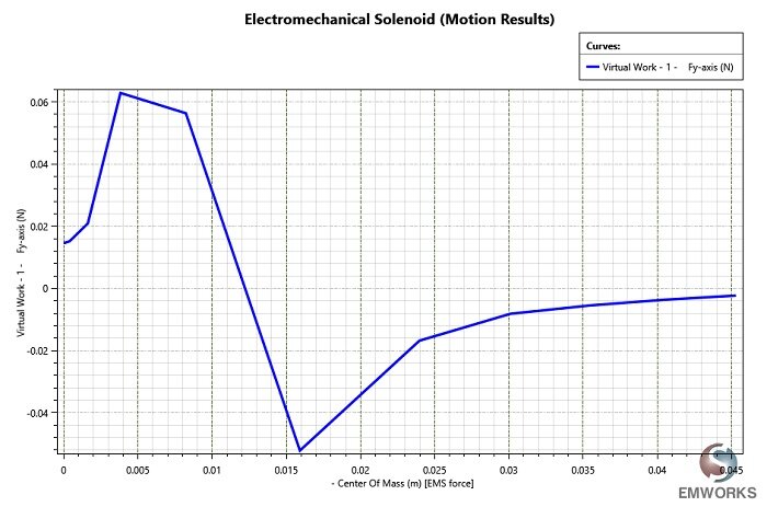
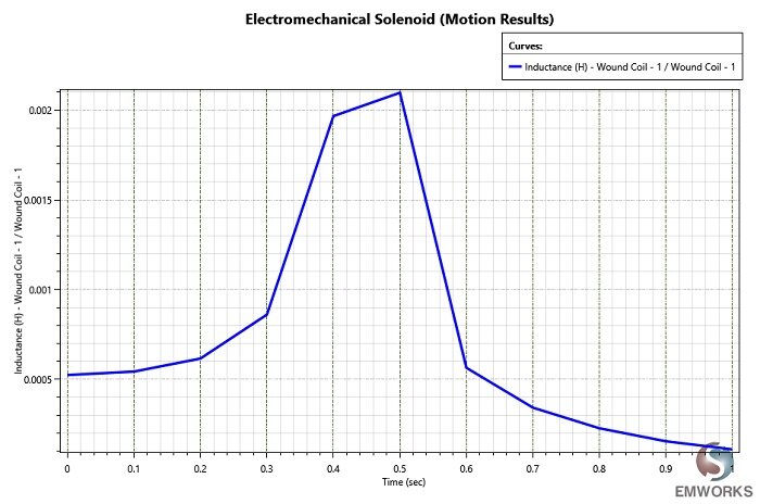
In motion studies, you can access various plots like flux, field, current, and more at each time step. These results can be viewed individually or animated to observe motion effects. Tabular results such as force, torque, inductance, and more are also available at each time step. You can plot these results against parameters like time, position, speed, and acceleration, such as torque vs. speed. Additionally, kinematic results like position vs. time can be visualized in the tabular results. Motion Manager provides comprehensive motion and kinematics results.
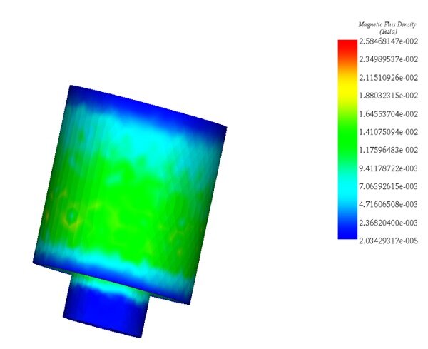
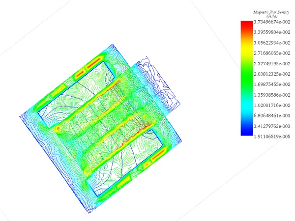
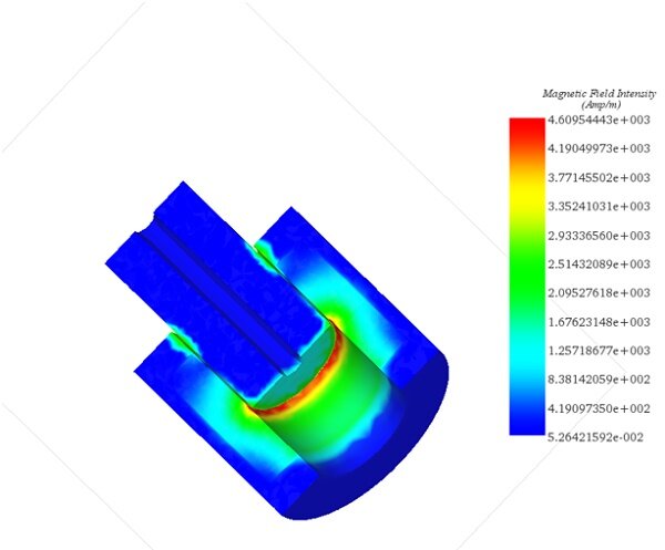
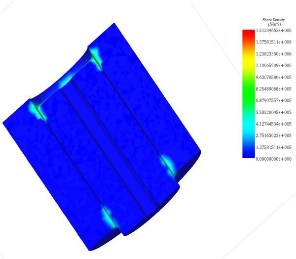
After running this simulation, we obtain results including Magnetic Flux Density (Figures 5 and 6), Magnetic Field Intensity (Figure 7), Applied Current Density, Force Density (Figure 8), Field Operation (B and H derivatives), and a result table with computed model parameters, force, and torque. EMS also supports 2D plots and motion animations.
Conclusion
This application note thoroughly examines the simulation of a linear solenoid, an electromagnetic device that transforms electrical energy into mechanical motion, and its detailed analysis through EMS and Motion. By iterating between EMS for magnetostatic analysis and SW Motion for physical movement, the study provides an in-depth look at how electrical currents induce a magnetic field, thereby moving a plunger within a coil. The simulation emphasizes the importance of material properties, particularly relative permeability, and the precise application of loads and restraints for accurate electromagnetic behavior modeling. Meshing strategies, crucial for efficient and accurate simulations, are tailored to the solenoid's design, enabling detailed analysis of magnetic flux density, field intensity, and force density. The results showcase the solenoid's performance, including magnetic flux distribution and the electromagnetic force exerted on the plunger, offering valuable insights into the device's operational efficiency. This comprehensive analysis underscores the solenoid's potential applications across various fields, from robotics to valve operation, highlighting the critical role of simulation in optimizing electromagnetic device design.