A 5G mmWave Waveguide Filter with Tuning Screws
The surge in 5G applications necessitates advanced RF and microwave filter components operating in mm-Wave frequency bands. HFWorks offers a comprehensive platform for designing, analyzing, and optimizing these components, supporting various structures including cavity, waveguide, coaxial, ceramic, and microstrips. In this study, we focus on a mmWave Waveguide band-pass filter design with Tuning screws, exploring the impact of screw depth on performance between 27GHz and 29GHz.
CAD Model
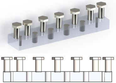
The optimized design of the mmWave WG filter, as outlined by [1], comprises seven standard WR-34 waveguide resonators separated by six cylindrical inductive irises and mounted with seven tuning screws. These screws are strategically placed at the center of each resonator, including one before and one after the iris from the wave port. They serve the purpose of fine-tuning the filter response, with each screw functioning akin to an inductive iris. Notably, the screws do not span end-to-end within the guide. Refer to Figure 1 for a visual representation of the 3D design.
Simulation and Results
The S-parameters solver within HFWorks operates within a frequency range of 27GHz to 29GHz. The simulation has unveiled the S-parameter results for the studied Band-pass filter, showcased in the 2D plot of return and insertion loss data versus frequency (refer to Fig. 2).
The return loss data from the simulation demonstrates satisfactory performance across the entire passband. Additionally, the S-parameter analysis reveals lower and upper stopband insertion loss values of -103.42 dB and -84.75 dB, respectively, at frequencies of 26 GHz and 30 GHz.
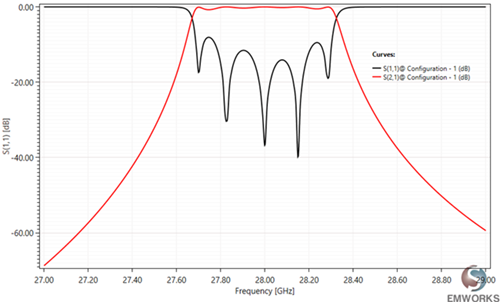
Fig. 2. Return and Insertion Loss Results vs Frequency
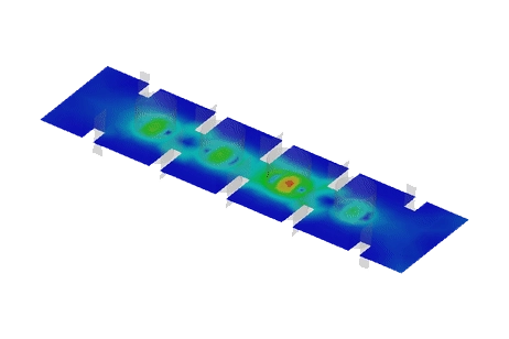
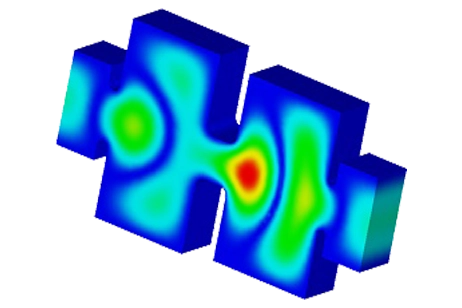
HFWorks automatically computed the electromagnetic field, showcasing the distribution and animation of the electric field versus phase at the resonance frequency of 28 GHz. Figure 3 illustrates this with an incident power of 1W.
Breakdown Level Analysis
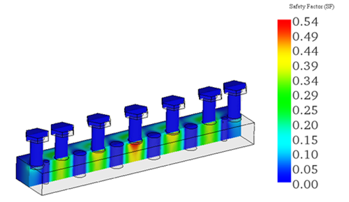
All dielectrics, including air, exhibit a maximum electric field strength threshold beyond which ionization occurs, leading to corona and sparking—a phenomenon commonly known as dielectric breakdown. This occurs when the applied power is excessive and/or when the spacing, such as the air gap between components, is insufficient.
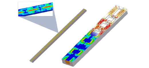
In our scenario, the penetration depth of the tuning screws, which determines the air gap to the waveguide bottom, can contribute to higher electric field strength levels. A cross-section presentation of the electric field safety factor distribution across the studied filter is depicted in the following plot, considering an incident power of 1 kW. Notably, a maximum safety factor of 0.54 is observed below the central tuning screw for the given phase.
Parametric Analysis: Filter S-parameter Sensitivity to Tuning Screws Depth
At a 5G frequency of 28 GHz, the wavelength measures approximately 10.71 millimeters, with 1 millimeter roughly equivalent to ?/10. Consequently, the filter's transmission properties are anticipated to be notably affected by the mechanical penetration depth of the screws within the waveguide.
A final parametric analysis is conducted to investigate the impact of this penetration depth on the resulting S-parameter performance of the bandpass filter. Given the symmetry of the filter design relative to the central screw, only four geometrical variables are optimized, as illustrated in the table below.
The obtained results are depicted in the following 2D plot, showcasing the return loss data versus frequency for four distinct scenarios. A considerable variation in S11 results is evident across the different scenarios, confirming the anticipated sensitivity of the studied filter to variations in the tuning element's depth.
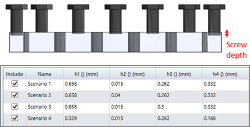
Fig. 5. Corresponding Screw Depth Combinations for Studied Scenarios
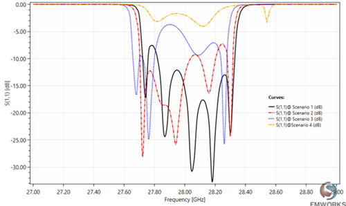
Fig 6. Return Loss Results vs Frequency and Scenarios
Conclusion
The application note explores the design, analysis, and optimization of a 5G mmWave waveguide filter with tuning screws using EMWorks simulation software. Through comprehensive simulations and parametric analyses, it is demonstrated how the mechanical penetration depth of tuning screws within the waveguide significantly impacts the filter's transmission properties, particularly its return and insertion loss performance across the 27GHz to 29GHz frequency range. The study highlights the critical role of tuning screw depth in achieving desired filter characteristics, with variations in screw penetration depth leading to notable changes in S-parameter performance. This sensitivity underscores the necessity of precise mechanical optimization in filter design to ensure optimal performance. Additionally, the analysis of dielectric breakdown due to electric field strength emphasizes the importance of considering safety factors in high-power applications.
References
[1]. Yuan Ping Lim ,Cheab Sovuthy ,Peng Wen Wong , (2018 ) " Design and Validation Of A 28 GHZ Millimeter-Wave Waveguide Filter for Future 5g Mobile Networks " , International Journal of Advance Computational Engineering and Networking (IJACEN) , pp. 48-50, Volume-6, Issue-2