A 3-phase PM Axial Flux Generator
Renewable energy, also known as clean energy, originates from naturally replenishing sources such as biomass, geothermal, hydropower, solar, and wind. Its production incurs no environmental debt and minimizes pollution. Historically, wood fulfilled the US energy needs until industrialization introduced coal, followed by petroleum and natural gas. Today, renewable energy accounts for 11% of total US energy demand, with wind energy being a significant contributor. Encouraged by government initiatives, renewable energy consumption doubled from 2000 to 2017, aiding in greenhouse gas reduction. The trend is expected to continue, with wind turbines and axial flux generators playing pivotal roles in this transition.
This article examines a three-phase PM axial flux machine, known for its efficiency, cost-effectiveness, and compact, lightweight design. Axial flux machines, particularly those with a coreless stator, are highlighted for their superior power density compared to radial flux counterparts, making them ideal for energy generation.
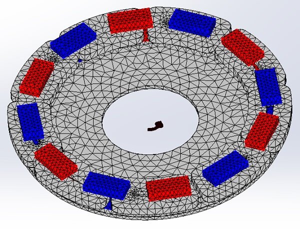
The model detailed in Figure 3 comprises a stator with nine stranded coils arranged into three phases, each containing three series coils with a total of 90 turns. This stator is positioned centrally between the rotor's two sides, each equipped with 12 permanent magnets and a laminated steel core. The use of Neodymium magnet 4212 for the permanent magnets, detailed in Table 1, and the BH curve of M-19 steel for the rotor cores, shown in Figure 4, underscore the machine's optimized magnetic properties for enhanced performance.
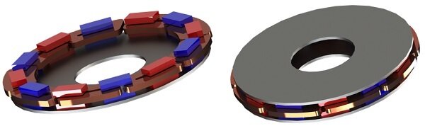
Figure 3 - 3D model of the simulated axial flux generator.
Table 1 - PM material properties
| Relative permeability | Remanence (Tesla) | Coercivity (A/m) | |
| N4212 | 1.205 | 1.35 | 891268 |
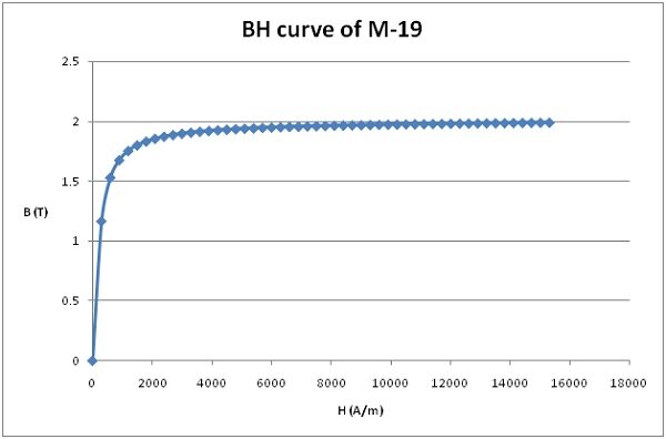
Figure 4 - BH curve of M-19.
Motion Coupling
The EMS system integrates electromagnetic fields with motion analysis, merging mechanical and magnetic forces. Specifically, for generators, the EMS Transient module, when linked with motion, calculates the induced voltage across each phase. This analysis considers a rotor speed of 1000rpm, with simulations conducted over a 0.01s timeframe. The results of this motion study are depicted in Figure 5.
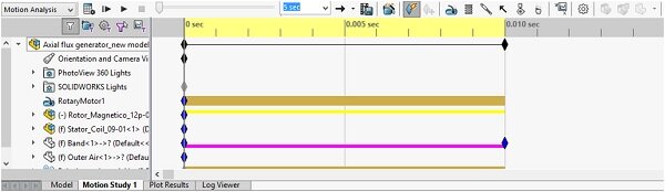
Figure 5 - Motion study.
EMS meshes geometry with tetrahedral elements, allowing adjustable mesh sizes for improved accuracy in specific areas. Below is the meshed model.
Results
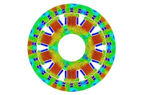
The EMS Transient module calculates instantaneous magnetic metrics like flux, force, torque, eddy currents, losses, voltages, and matrices for resistance and inductance. Figures 7 and 8 display the magnetic flux density via fringe and vector plots in the model and magnets at 5.5ms, showing the PM's axial magnetization. Figure 9 depicts the magnetic field at 10ms. Figures 10 and 11 show the rotor's angular displacement and velocity, maintaining a constant speed of 1000 rpm.
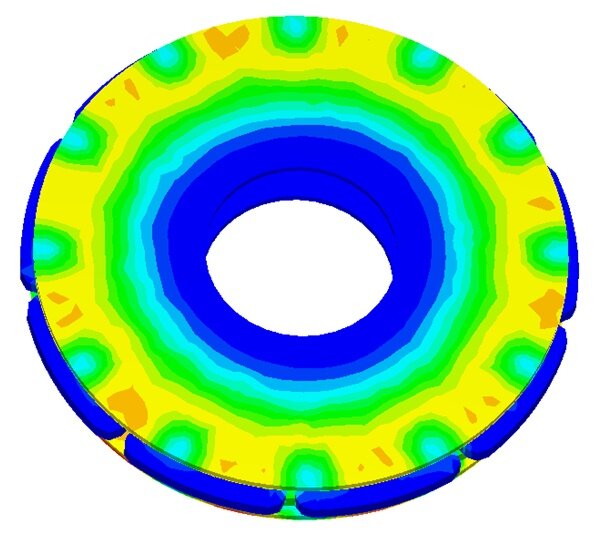
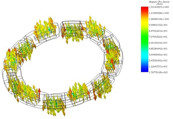
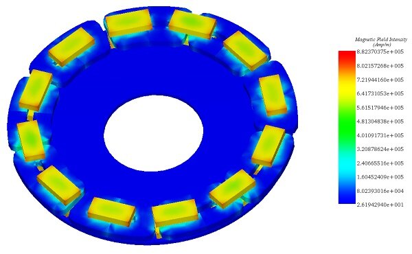
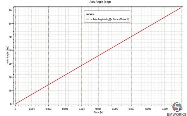
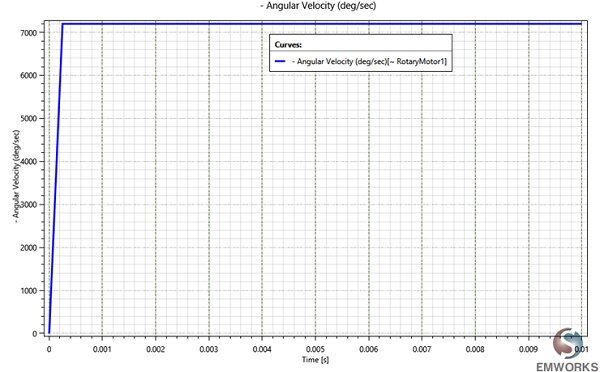
Figure 12 illustrates the induced voltage across each phase over time, revealing a sinusoidal pattern with peaks reaching 37V. This waveform's frequency is derived from its period, calculated as 0.008333 seconds from the graph, resulting in a frequency of 120Hz. The axial flux generator's induced voltage characteristics are thus defined by an amplitude of 37V and a frequency of 120Hz. Figure 13 displays the flux linkage versus rotor angle, mirroring the sinusoidal shape of the induced voltages. The phase resistance is constant at 0.45 Ohm, owing to the use of stranded coils (minimizing eddy currents) and electrically non-conductive steel. The static inductance is measured at 0.146 H, with the dynamic inductance of each phase detailed in Figure 14.
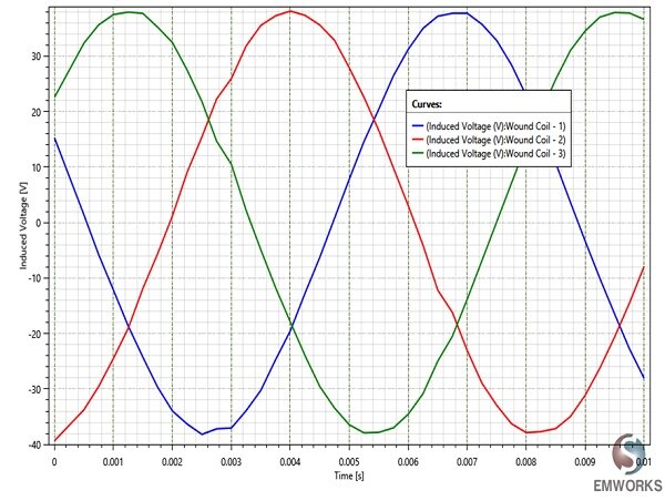
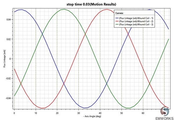
Figure 13 - Flux linkage versus rotor angle
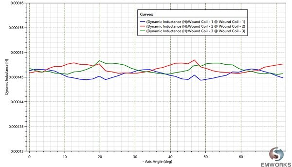
Figure 15 shows an animation of the magnetic flux density versus time.
Conclusion
This application note delves into the design, simulation, and analysis of a 3-phase Permanent Magnet (PM) Axial Flux Generator, a pivotal component in renewable energy systems, particularly wind energy. The study underscores the generator's construction, featuring a stator with nine stranded coils arranged in three phases, and a rotor on either side with 12 permanent magnets, optimizing magnetic properties for enhanced performance.
The simulation, conducted using the EMS system's Transient module coupled with motion analysis, evaluates the induced voltage across each phase at a rotor speed of 1000rpm. Key outcomes include magnetic flux density, field intensity, eddy currents, and angular displacement, with results indicating a constant rotor speed and a sinusoidal induced voltage pattern peaking at 37V with a frequency of 120Hz. This highlights the generator's capability to produce a stable and efficient electrical output suitable for renewable energy applications.
The application note exemplifies the utility of integrating electromagnetic field simulation with mechanical motion analysis to predict the performance of axial flux generators. By focusing on the induced voltage characteristics and analyzing the generator's magnetic and electrical properties, this study contributes valuable insights into the development of more efficient and compact generators for renewable energy systems, furthering the transition towards cleaner energy sources.
References
[1]: https://www.eia.gov/energyexplained/?page=renewable_home
[2]: Pop AA, Jurca F, Oprea C, Chirca M, Breban S, Radulescu, MM. Axial-flux vs. radial-flux permanent-magnet synchronous generators for micro-wind turbine application. In: 15th European conference power electronics and applications; 2014; p. 1–10.
[3]: Caricchi, F. Crescimbini, O. Honorati, G. Lo Bianco, E. Santini.Performance of coreless- winding axial-flux permanent-magnet generator with power output at 400 Hz, 3000 r/min. IEEE Trans Ind Appl, 34 (1988), pp. 1263-1269