Permanent Magnet Axial Flux Generator
This application note investigates a PM magnet axial flux generator's performance under both load and no-load conditions. Utilizing EMS, we analyze key metrics such as back EMF, short circuit response, current and voltage waveforms across varying loads, and eddy and iron losses. Additionally, we derive winding parameters to conduct a comprehensive performance analysis of the machine.
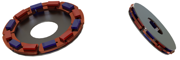
Figure 1 depicts the simulated axial flux permanent magnet machine, featuring a double-sided rotor coreless design with 24 poles composed of N42 permanent magnets. This generator type finds applications in transportation as well as energy production.
Simulation and Results
1- No Load Analysis
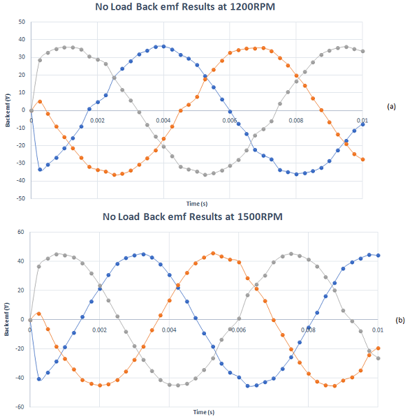
In the no-load analysis, back EMF results are computed for each phase across various rotor speeds. Figures 2a) and 2b) illustrate the back EMF results for all three phases at 1200RPM and 15000RPM, respectively. The computed back EMF signifies a balanced system with a frequency of approximately 150Hz. At 1200RPM, the peak value of the signal is approximately 36V, while at 15000RPM, it increases to around 45V.
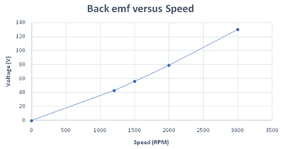
The generator's back EMF increases linearly with rotor speed. Figure 3 illustrates this linear dependency between the output voltage and speed.
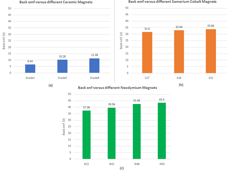
Speed is not the sole factor influencing the generator output voltage. Magnet type, specifically magnet remanence, significantly impacts the back EMF. Figures 4a), 4b), and 4c) demonstrate how the back EMF varies with different magnet types. It is minimal when using ceramic magnets and maximal with neodymium magnets. This discrepancy arises from the low and high remanence of ceramic and neodymium magnets, respectively. For instance, the Br values for ceramic grade 1 and N55 neodymium magnets are 0.22T and 1.47T, respectively.
As evidenced by Figure 4, the generator back EMF increases with speed. Consequently, low remanence magnets can be employed during high-speed operations to mitigate the risk of overvoltage.
2- Short circuit Response
Short circuit analysis is crucial in the study of electrical machines as it predicts the high currents generated during short circuit occurrences. Thus, the short circuit response of the 3-phase axial flux generator was examined. Figure 5 displays the simulated short circuit schematic, conducted using EMS circuit simulator, with each winding representing one phase.
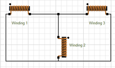
Figure 6 depicts the generator currents under short circuit conditions, while Figure 7 showcases the generator currents under normal conditions. A notable observation is that short circuit currents are nearly ten times greater than those during normal operation. This insight aids in calculating the maximum current tolerable by protective fuses.
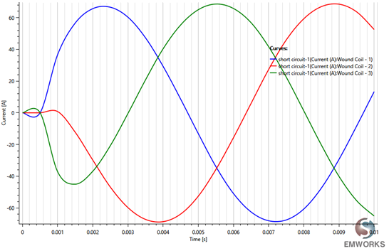
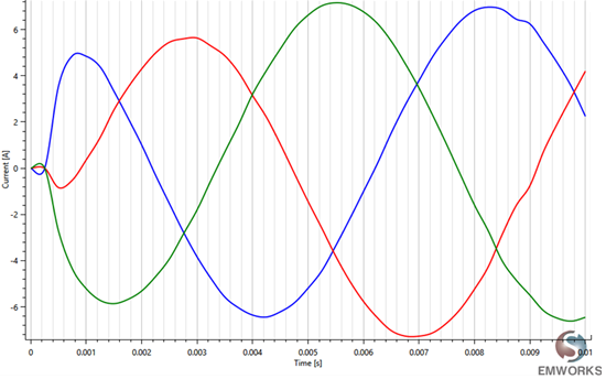
Figure 7 - Normal operation currents
3- Load Analysis
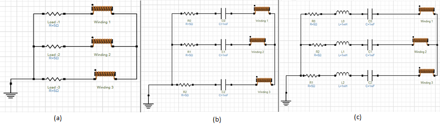
The load test of the axial flux generator is conducted for various load types utilizing EMS circuit simulator. Figures 8a), 8b), and 8c) display the different simulated circuits, encompassing resistive load, RC load, and RLC load, all connected in a star configuration.
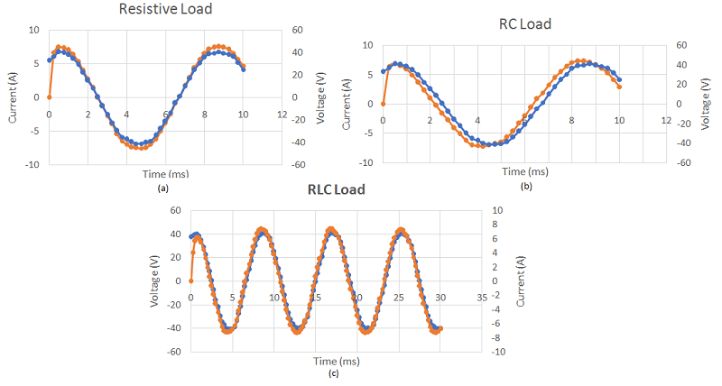
Current and voltage results for each load type are computed and plotted in Figures 9a), 9b), and 9c). In the case of resistive load, they exhibit the same phase shift, while there is a slight delay observed in the other load types.
Electromagnetic losses
During load operation, significant electromagnetic losses occur, impacting the machine's efficiency and potentially increasing maintenance costs. Therefore, it's crucial to meticulously study these quantities during the design of electrical machines, including motors and generators. EMS predicts eddy, iron, and copper losses.
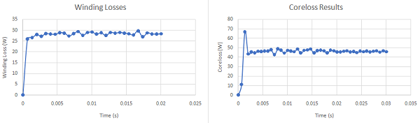
Winding losses are depicted in Figure 10, while core loss results are shown in Figure 11. The relatively high core loss is attributed to the frequency of the voltage generated by this machine.
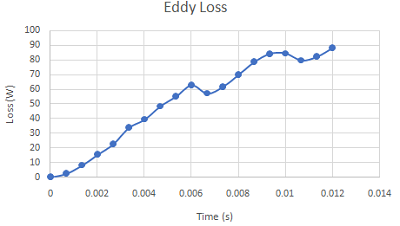
If the machine's ferromagnetic cores are not laminated and are instead made of solid bodies, significant eddy currents are anticipated. Therefore, it's essential to examine them separately from core loss calculations. Figure 12 illustrates the evolution of eddy losses in the rotor cores over time, while an animation of the eddy currents mapping is presented in Figure 13.
Conclusion
The application note investigates the performance of a Permanent Magnet (PM) axial flux generator under load and no-load conditions, employing EMS for analysis. Key metrics such as back EMF, short circuit response, and electromagnetic losses are examined. Results indicate a linear relationship between back EMF and rotor speed, with magnet type significantly impacting back EMF due to varying remanence levels. Short circuit analysis reveals significantly higher currents compared to normal operation, aiding in protective fuse selection. Load tests for resistive, RC, and RLC loads demonstrate phase shift variations and slight delays. Electromagnetic losses, including winding, core, and eddy losses, are studied to understand their impact on efficiency and maintenance costs. Notably, solid ferromagnetic cores may lead to significant eddy currents, necessitating separate examination. Overall, the study provides comprehensive insights into the axial flux generator's behavior, facilitating informed design decisions for optimal performance and reliability.