What is a magnetizer?
The magnetizer also referred to as a magnetic flux concentrator, enhances magnetic control by amplifying the magnetic flux in specific regions of a workpiece. Commonly utilized in induction heating applications, magnetizers serve as an electromagnetic shield, preventing unwanted heating in surrounding areas. Their function mirrors that of a transformer's core, utilizing materials characterized by low power loss and high permeability to achieve efficient flux concentration.
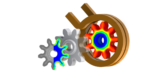
![The effect of magnetizer on the magnetic flux field distribution around the electric conductor [1].](/ckfinder/userfiles/images/The-effect-of-magnetizer-on-the-magnetic-flux-field-distribution-around-the-electric-conductor%5B1%5D.jpg)
Figure 1 - The effect of the magnetizer on the magnetic flux field distribution around the electric conductor [1]
CAD Model
To enhance the efficiency of spot induction heating, the model integrates a U-shaped coil with a Ferrite magnetizer, aimed at boosting the workpiece's heating rate and achieving uniform temperature distribution. The CAD design detailing this setup is presented in Figure 2.
A Finite Element Method (FEM) analysis conducted with the EMS tool assessed the magnetizer's impact on the induction heating process. Utilizing the AC Magnetic module of EMS, coupled with transient thermal analysis, the study explored electromagnetic and temperature distributions to optimize heating performance.
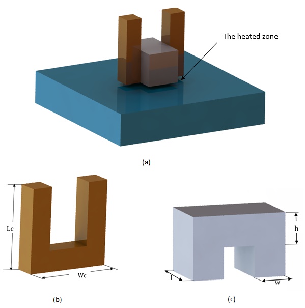
Figure 2 - a)3D design of the studied model b)coil and c)the magnetizer
Table 1 - Components' dimensions [1]
| Component | Dimensions (mm) | ||
| Workpiece | W | L | H |
| 100 | 100 | 20 | |
| Coil | Wc | Lc | Cross section |
| 40 | 40 | 10x10 | |
| Magnetizer | w | l | h |
| 10 | 20 | 10 | |
| Air Gap between workpiece and coil | 2 | ||
Simulation setup
EMS facilitates multi-physics simulation through the coupling of magnetic and thermal fields, enabling accurate modeling of the induction heating process. The setup for such a simulation involves several critical steps.
1. Select the appropriate materials
The simulated model includes a copper coil, a ferrite magnetizer, and a carbon steel workpiece. The essential properties of these components are summarized in Table 2.
| Part | Material | Density (Kg/ |
Magnetic permeability |
Electrical conductivity (S/m) |
Thermal conductivity (W/m.K) |
Specific heat capacity (J/Kg.K) |
| Workpiece | Carbon Steel (AISI1045) | 7870 | K (T): Figure 3.3 | |||
| Coil | Copper (Cu) | 8900 | 0.99 | 5.7 E+07 | 385 | 390 |
| Magnetizer | Ferrite (Ni Zn) | 4900 | Initial permeability: 1500 Relative permeability: 1.19 E+08 |
0 | 5 E-06 | 750 |
The material chosen for the workpiece exhibits temperature-dependent properties, which are detailed in the figures provided below.
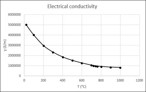
Figure 3.1 - Electrical conductivity of AISI 1045 Steel
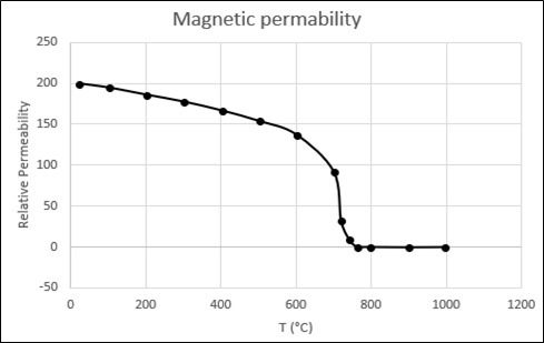
Figure 3.2 - Magnetic permeability of AISI 1045 Steel
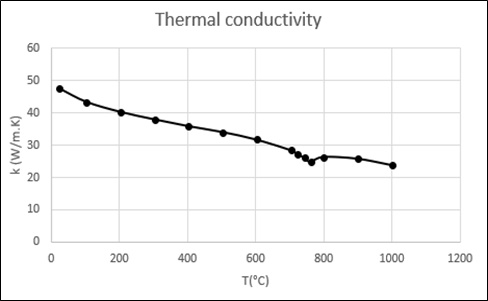
Figure 3.3 -Thermal conductivity of AISI 1045 Steel
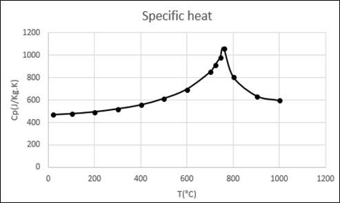
Figure 3.4 - Specific heat of AISI 1045 Steel
2. Electromagnetic Input
The inductor coil is defined as a single-turn solid coil capable of supporting a maximum current of 1200 A rms at a frequency of 30 kHz.
3. Thermal Input
The workpiece is set to an initial temperature of 20°C. Thermal convection is applied to the air body, with the ambient temperature at 25°C and a convection coefficient of 10 W/m²K.
4. Meshing
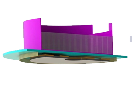
For each FEM simulation, the accuracy of the results and the time it takes to solve are closely linked to the quality of the mesh. EMS provides a Mesh Control feature that allows for the adjustment of mesh size in specific regions of the model. In this case, a fine mesh size was selected for the coil and the top surface of the workpiece, ensuring detailed and accurate simulation outcomes. Figure 4 illustrates the entire model with the applied mesh.
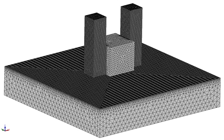
Figure 4 - Meshed model
Results
After 7 seconds of induction heating, the simulation results illustrate the magnetic flux distribution's vector plot within the magnetizer at the heating cycle's conclusion. The magnetizer's high permeability material focuses the magnetic flux around the electric conductor and through its core. This containment minimizes field dispersion outside the core, subjecting the heated area to an intensified magnetic field. Consequently, the high temperature is confined to a targeted area, reducing the power required for the workpiece's heating treatment, demonstrating efficient energy use and precise heating control.
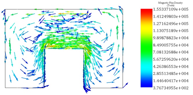
Figure 5 - Vector plot of the magnetic flux density after 7s
Figure 6 displays the vector plot of the eddy current distribution within the coil and the workpiece, where the eddy currents reach a maximum of 1.19E+08 A/m² on the workpiece's top surface and 1.02E+09 A/m² within the coil. This distribution leads to highly heated zones at the center of the workpiece's surface, aligning the simulation results closely with those found in Reference [1], thereby confirming the effectiveness of the induction heating process in focusing energy precisely where needed.
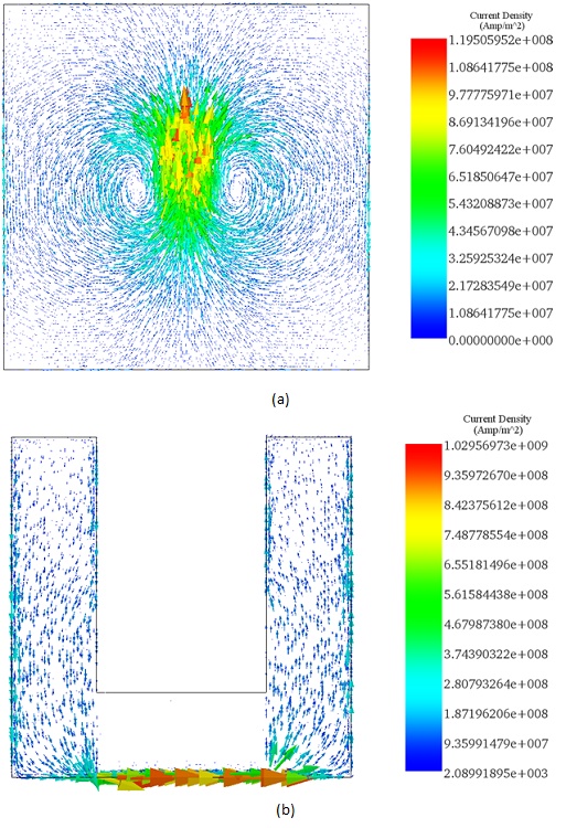
Figure 6 - Eddy current density after 7s across a)the workpiece and b)the coil
Figure 7 showcases the temperature distribution across the top surface of the workpiece, indicating that the highly heated zone at the center achieved a maximum temperature of 850 °C. This confirms that the induction heating process successfully reached the required level of heating, demonstrating precise temperature control and efficiency in the heating treatment.
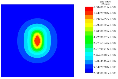
Figure 7 - Temperature distribution across the workpiece
Conclusion
In conclusion, this application note elucidates the pivotal role of magnetizers, also known as magnetic flux concentrators, in refining magnetic control by amplifying magnetic flux within specific regions of a workpiece. Primarily employed in induction heating applications, magnetizers act as electromagnetic shields, preventing unintended heating in surrounding areas. Functioning akin to a transformer's core, they employ materials characterized by low power loss and high permeability to achieve efficient flux concentration. The study integrates a U-shaped coil with a Ferrite magnetizer to enhance the efficacy of spot induction heating, aiming to boost the workpiece's heating rate and achieve uniform temperature distribution. Through Finite Element Method (FEM) analysis using EMS, the study evaluates the magnetizer's impact on induction heating, providing insights into electromagnetic and temperature distributions for optimized heating performance. Results indicate precise deflection patterns and magnetic flux distributions, aligning closely with experimental data from previous studies. Notably, the induction heating process successfully reaches the desired temperature, demonstrating precise temperature control and energy efficiency. Overall, this research contributes to advancing induction heating technology, emphasizing the significance of magnetizers in achieving precise and efficient heating treatments.
References
[1]. Gao, Kai, et al. "Effect of magnetizer geometry on the spot induction heating process." Journal of Materials Processing Technology 231 (2016): 125-136.