A DC Contactor
Magnetic actuators convert electrical energy into mechanical motion through electromagnetic fields, categorized into rotary and linear types. DC actuators, like electromagnetic contactors, are crucial in electrical switchgear, featuring permanent magnets, solenoids, and ferromagnetic parts.
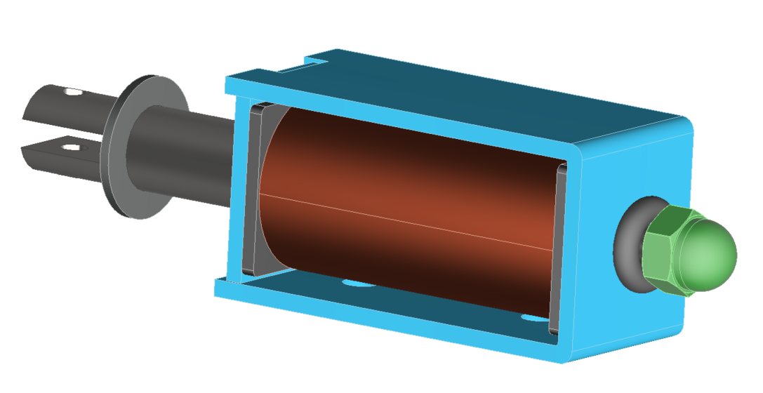
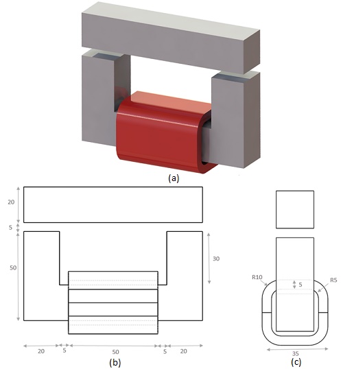
In pursuit of energy efficiency, a DC contactor with electronic control and permanent magnets has gained attention for its energy-saving and noise-reducing benefits. This study focuses on a three-part DC contactor with a non-linear ferromagnetic core, movable and fixed components, and a DC copper coil, as shown in Figure 1.
CAD Model
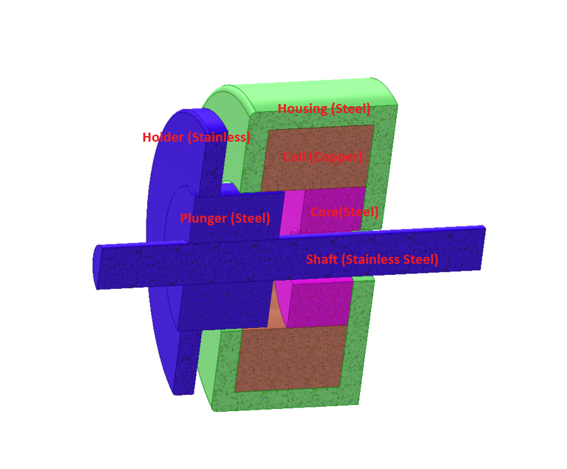
The Magnetostatic module within EMS is utilized to determine the force generated across the air gap separating the lower and upper moving segments of the nonlinear ferromagnetic core. This model maintains translational invariance along the z-axis. The work coil consists of 1000 turns of copper wire carrying a 2A DC current. The air gap between the fixed and moving components is set at 5 mm. Refer to Figure 2 for the detailed 3D design of the model along with its dimensions.
The physical properties of the copper used for the work coil, are defined in Table 1 below:
Material | Density ($$ \frac{\text{Kg}}{\text{m}^3} $$) | Magnetic permeability | Electrical conductivity (S/m) | Thermal conductivity (W/m.K) | Specific heat capacity (J/Kg.K) |
| Copper (Cu) | 8900 | 0.99 | 6 E+07 | 385 | 390 |
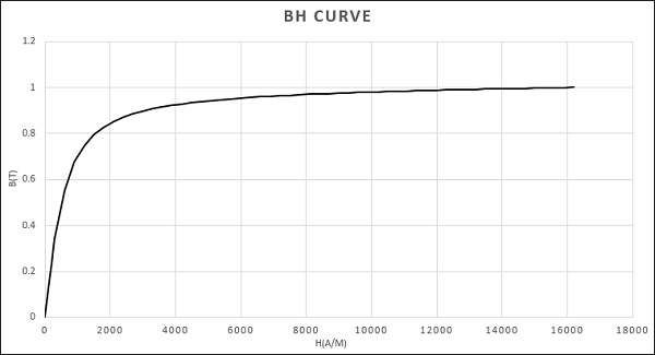
The core is made of nonlinear ferromagnetic material, for which the BH relation can be defined by the expression below:
$$ B(H) = \mu_0 H + \frac{2 J_s}{\pi} \arctan\left( \frac{\pi (\mu_r - 1) \mu_0 H}{2 J_s} \right) $$ [1]
With: $$ J_s = 1 \, \text{Tesla} $$: Saturation value of B field
$$ \mu_r = 1000 $$ : Initial permeability
$$ \mu_0 = 4 \pi \times 10^{-7} $$ : Vacuum permeability
The corresponding BH curve is defined by the next 2D plot:
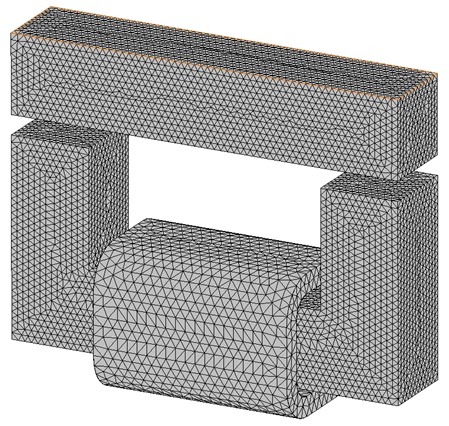
Effective mesh control is paramount for accurate Finite Element Method (FEM) simulations. The quality of results and computational efficiency heavily rely on mesh size optimization. EMS provides users with the Mesh control feature to precisely adjust mesh size on solid bodies and faces. In this example, a fine mesh control was implemented on our model to enhance result precision.
Results
The magnetic contactor functions by directing a DC current through a multi-turn coil, generating a static magnetic flux. This flux density then applies a constant magnetic force to the moving part of the ferromagnetic core. The figures below illustrate the results obtained from the Magnetostatic simulation.
1. Electromagnetic analysis
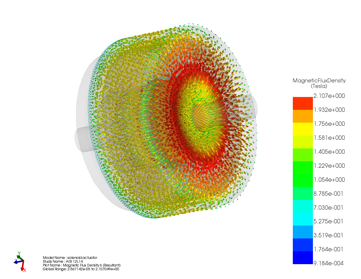
The flux density distribution across the ferromagnetic core reaches a peak value of 0.98 T with a current excitation of 2A, as depicted in Figure 5.
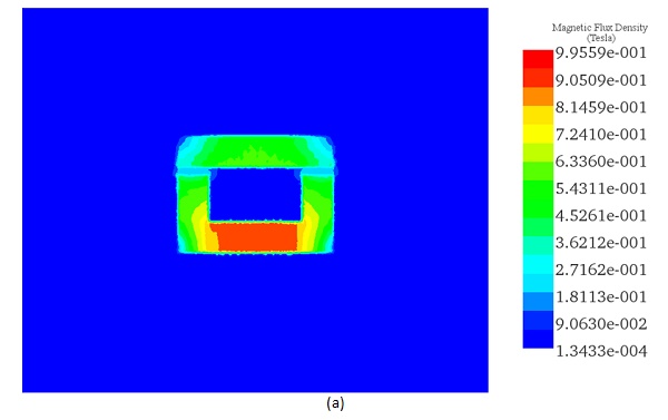
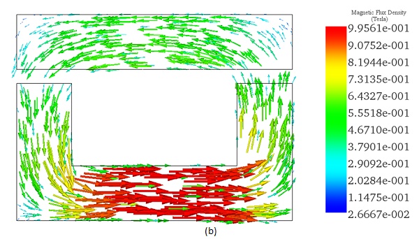
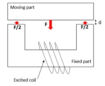
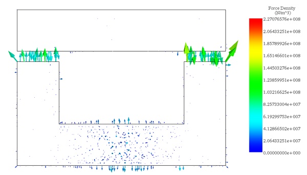
Figure 6 illustrates the distribution of magnetic force across the area between the moving and fixed parts, computed within EMS using the virtual work feature.
2. Motion Analysis
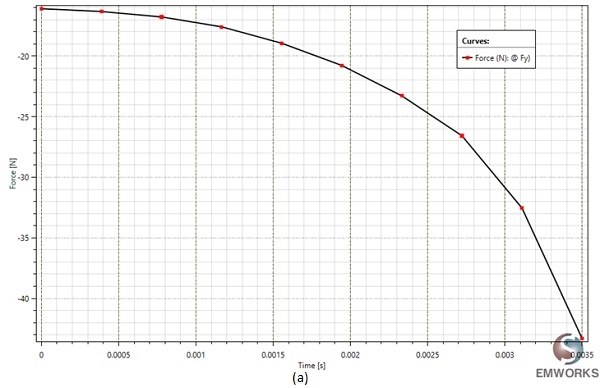
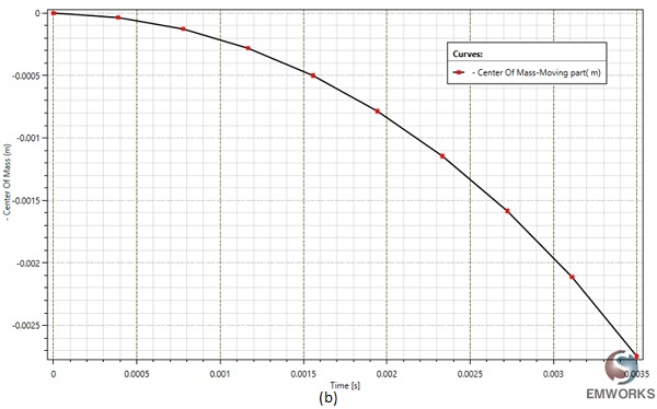
At a fixed current excitation of 2A and after t=3.5 ms, the simulation yields the following results: Figure 7 illustrates the fluctuation of the generated force and the center of mass position of the moving part over time. This data offers insight into the variation of the air gap between the two components of the magnetic contactor, diminishing from d=5mm to d=2.3mm.
The motion analysis conducted by EMS computes the instantaneous linear velocity, showcased in the EMS results table. At t=3.5ms, it reaches a peak value of 1.77 m/s, directly proportional to the generated force.
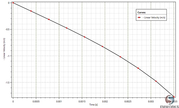
Figure 8 - Linear velocity variation versus time.
3. Parametric analysis
EMS facilitates comprehensive analysis of the electromagnet by enabling the exploration of various scenarios within a single study. This capability is leveraged to evaluate the generated force of the contactor concerning both current excitation and the air gap distance between its parts.
The table below illustrates the selected parametric variables:
| Scenarios | Air gap length (mm) | Current (A) |
| scenario 1 | 1 | 1 |
| scenario 2 | 2 | 1 |
| scenario 3 | 3 | 1 |
| scenario 4 | 4 | 1 |
| scenario 5 | 1 | 2 |
| scenario 6 | 2 | 2 |
| scenario 7 | 3 | 2 |
| scenario 8 | 4 | 2 |
| scenario 9 | 1 | 3 |
| scenario 10 | 2 | 3 |
| scenario 11 | 3 | 3 |
| scenario 12 | 4 | 3 |
| scenario 13 | 1 | 4 |
| scenario 14 | 2 | 4 |
| scenario 15 | 3 | 4 |
| scenario 16 | 4 | 4 |
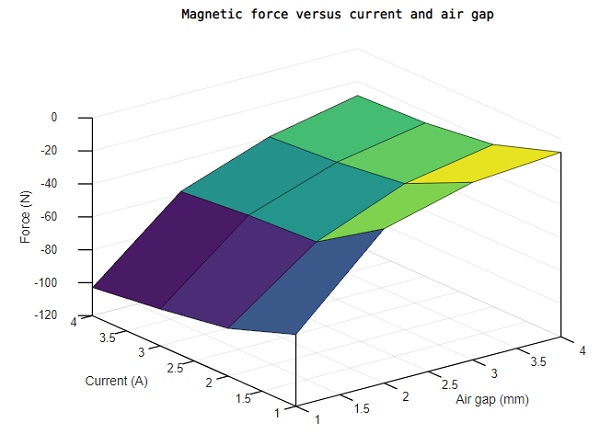
By systematically varying both the current and air gap distance, EMS calculates and visualizes the magnetic force acting on the upper moving part of the contactor. As depicted in Figure 10, the 3D plot illustrates how the resultant force intensifies with a higher current and a reduced gap distance.
This magnetic actuator demonstrates significant magnetic forces while consuming minimal power, making it a preferred choice among switchers compared to conventional types.
Conclusion
This application note delves into the analysis and optimization of a DC contactor using EMS software for magnetic and motion analysis. It presents a detailed examination of a three-part DC contactor that incorporates electronic control and permanent magnets, aimed at improving energy efficiency and reducing noise in electrical switchgear. By simulating the electromagnetic behavior of the contactor, including the force generated across an air gap in a nonlinear ferromagnetic core, the study provides insights into the performance enhancements offered by the design. The contactor's operation is characterized by the application of a DC current through a copper coil, generating a static magnetic flux that actuates the moving part of the core. Results from the Magnetostatic simulation reveal a peak flux density of 0.98 T at a 2A current excitation. Motion analysis further quantifies the force and velocity of the moving component, illustrating the contactor's dynamic response to varying current excitations and air gap distances. This comprehensive analysis underscores the potential of the new DC contactor design to deliver significant improvements in energy efficiency and operational noise reduction, marking a significant advancement in electromagnetic actuator technology for electrical switchgear applications.
References
[1]. Le Van, V., 2015. Développement de formulations intégrales de volume en magnétostatique (Doctoral dissertation, Université Grenoble Alpes).
[2]. Perin, Arnaldo JosÉ. "An electronic control unit for reducing contact bounce in electromagnetic contactors." IEEE Transactions on Industrial Electronics 55.2 (2008): 861-870.