Electric Fuse
In the realm of electronics and electrical engineering, a fuse stands as a vital electrical safety mechanism, designed to safeguard electrical circuits from excessive currents. At its core, a fuse consists of a metal wire or strip specifically engineered to melt when subjected to an excessive current flow, effectively interrupting the circuit. This sacrificial device serves a crucial role; once a fuse has undergone the melting process, it transforms into an open circuit, necessitating replacement or rewiring. Figure 1 illustrates an automotive application of a fuse, while Figure 2 showcases a fuse tailored for high-power applications.
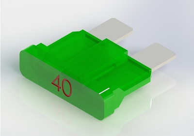
Figure 1 - Example of vehicle fuse
![A 115 kV high-voltage fuse in a substation near a hydroelectric power plant [1]](/ckfinder/userfiles/images/A-115-kV-high-voltage-fuse-in-a-substation-near-a-hydroelectric-power-plant%20%5B1%5D.jpg)
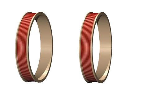
Figure 2 - A 115 kV high-voltage fuse in a substation near a hydroelectric power plant [1]
Thermal-electrical modeling of an automotive fuse
Joule heating occurs as a result of the transformation of electrical energy dissipated by current flow through a conductor into thermal energy. EMS offers a comprehensive thermal-electrical analysis, perfectly suited for tackling such scenarios. In this example, we demonstrate the utilization of this capability to model the heating process within an automotive electrical fuse due to a consistent electrical current.
Automotive electrical fuses are pivotal devices in vehicle circuit protection. They come in various current ratings and are meticulously designed. When the operating current surpasses the designated level for an extended duration, the heat generated from electrical conduction induces the melting of the metal conductor, leading to the disconnection of the circuit.
An automotive electrical fuse typically comprises a metal conductor, often zinc, encased within a transparent plastic housing. It's important to note that, for the finite element model depicted in Figure 3, we exclude the representation of the plastic housing, as it primarily serves to shield and support the slender conductor.

Figure 3 - 3D model of simulated fuse
In this particular instance, we have harnessed the Electric Conduction solver, which is seamlessly integrated with thermal analysis. This simulation yields a comprehensive set of results, encompassing Electric field, current density, potential, safety factor, as well as Temperature and Heat flux plots.
Simulation setup
Upon establishing a coupled Electric Conduction and thermal study within EMS, it is imperative to adhere to these four crucial steps:
-
Apply the proper material for all solid bodies.
-
Apply the necessary electromagnetic inputs.
-
Apply the necessary thermal inputs.
-
Mesh the entire model and run the solver.
Materials
The fuse is constructed from zinc, a material characterized by isotropic electrical and thermal conductivity that exhibits temperature-dependent behavior, as depicted in Figure 5.
Table 1 - Material properties
| Components / Bodies | Material | Relative permittivity | Mass density (Kg/m^3) | Specific Heat (J/Kg*K) |
| Fuse | Zinc | 1 | 7140 | 388.1 |
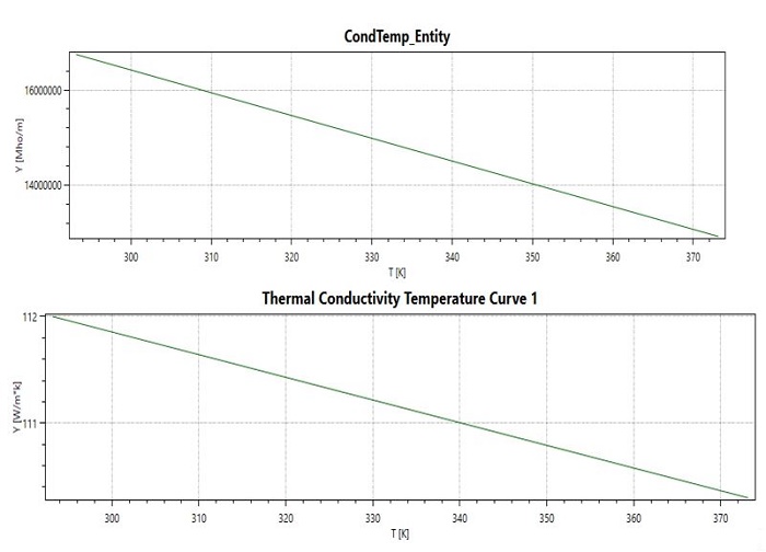
Figure 4 - Electric and thermal conductivity curves
Electromagnetic inputs
In this study, fixed voltages as shown in Table 2 are the only electromagnetic inputs.
| Name | Fixed Voltage |
| Face 1 | 0.08 V |
| Face 2 | 0 V |
.jpg)
Thermal inputs
In this illustrative case, natural convection is employed on both the upper and lower surfaces of the fuse.
.jpg)
Meshing
Meshing represents a pivotal phase in the design analysis process. EMS calculates an optimal global element size by considering various factors like the model's volume, surface area, and intricate geometric features. The resulting mesh size, including the number of nodes and elements, is contingent upon a multitude of aspects, including the model's geometry, dimensions, specified element size, mesh tolerance, and mesh control.
During the initial phases of design analysis, when approximations may suffice, opting for a larger element size can expedite the solution process. However, for situations demanding a higher degree of precision, a smaller element size becomes imperative to attain a more accurate solution.

Figure 7 - Meshed Model
Electrothermal results
The transient electric outcomes stem from the temperature-dependent electrical conductivity and the integration with transient thermal analysis. The entire solution process is configured with a duration of 150 seconds and a time increment of 15 seconds.
Figure 8 provides a visualization of the electric field within the fuse at the 75-second mark. Additionally, Figure 9 offers a 3D vector plot representing the current density within the fuse. Notably, the highest current values are concentrated within the fuse element itself.
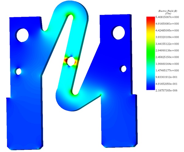
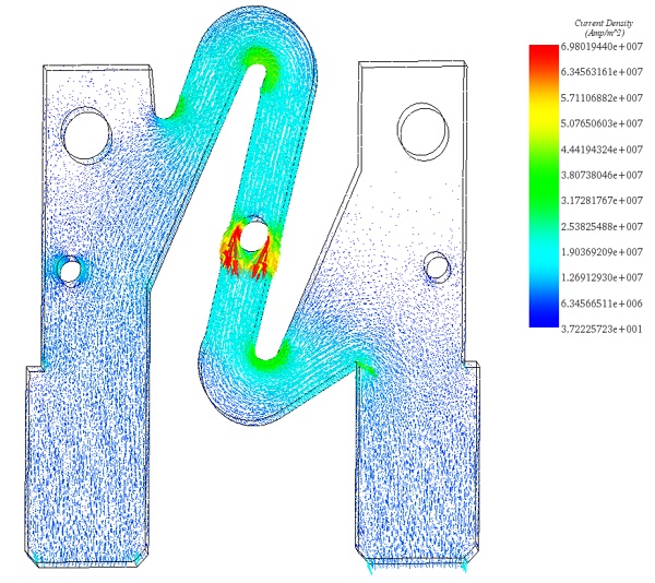
Figure 9 - Current density distribution in the fuse (vector plot)

Figure 10 - Electric potential
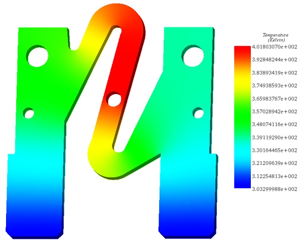
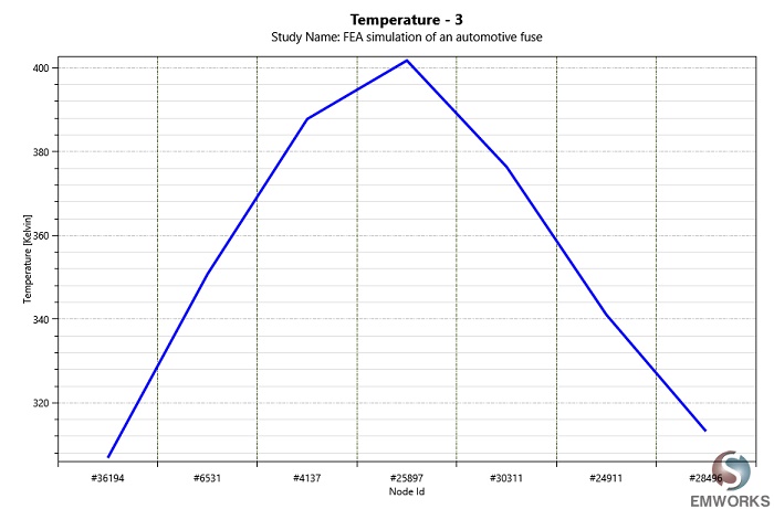
Figure 11 showcases the temperature distribution within the fuse, illustrating that the highest temperatures are concentrated within the fuse element. This temperature increase is attributed to the elevated current density occurring in the same vicinity. Figure 12, on the other hand, presents a plot depicting the temperature variation as a function of distance along the middle section of the fuse.
Conclusion
This application note delves into the essential function of electric fuses in circuit protection, highlighting their capability to prevent excessive currents from damaging electrical circuits. It specifically focuses on the thermal-electrical modeling of an automotive fuse, employing EMS to simulate the fuse's behavior under persistent electrical currents. The study underscores the importance of fuses in automotive applications, where they are designed to melt and thus disconnect the circuit when the operating current exceeds safe levels for too long, preventing potential hazards.
The simulation process outlined involves selecting appropriate materials, applying electromagnetic and thermal inputs, and conducting mesh analysis to ensure accurate modeling. Zinc, chosen for its isotropic electrical and thermal conductivity, serves as the primary material for the fuse, with simulations excluding the plastic housing to concentrate on the metal conductor's thermal response.
Results from the Electric Conduction solver, integrated with thermal analysis, offer insights into the electric field, current density, potential, and temperature within the fuse. The simulation reveals how areas of high current density correlate with temperature spikes, leading to the fuse's melting. This behavior underscores the fuse's role as a safety device, transforming into an open circuit upon melting, which necessitates replacement or rewiring. Through detailed modeling and analysis, the note provides a comprehensive understanding of fuse operation, emphasizing their critical role in safeguarding electrical systems.