Helmholtz Coil
A Helmholtz coil, named after physicist Hermann von Helmholtz, consists of two solenoid electromagnets aligned on the same axis to create a nearly uniform magnetic field (Figure 1). These coils can also cancel external magnetic fields, including the Earth's.
A Helmholtz pair comprises two identical circular magnetic coils placed symmetrically along a common axis, each carrying the same electric current.
Uniform magnetic fields play a vital role in plant and seed research at both physical and molecular levels. The Helmholtz coil, designed for bioelectric experiments, generates a large uniform magnetic field ideal for biomagnetic studies. It can treat 200 seeds simultaneously and is driven by both AC and DC currents. Additionally, it withstands prolonged use to accommodate experiments that span several days.
The equation for the field strength at the center of the coils is:
![]()
B=magnetic field, in gauss
R=radius of coils, in meters
N=number of turns of wire on each coil
I=current through each turn of wire, in amperes
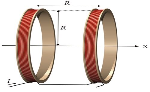
Figure 1 – model of Helmholtz coil
CAD model of Helmholtz coil
The 3D model depicted in Figure 2 was designed using CAD software, and you can find detailed Helmholtz coil parameters and dimensions in Table 1.
Table 1 – Parameters and dimensions of Helmholtz coil
| Diameter (cm) | |
| Coil diameter | 47.5 |
| Coil width | 100 |
| Coil depth | 53 |
| Coil height | 130 |
| Number of turns | 100 |
| Gauge | 10 |
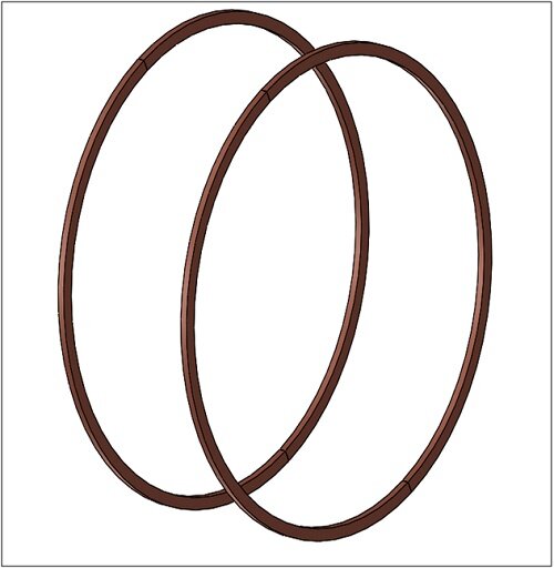
Figure 2 - 3D model of Helmholtz coil
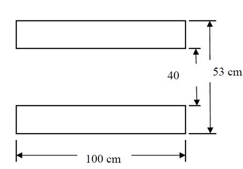
Figure 3- top view of the coil
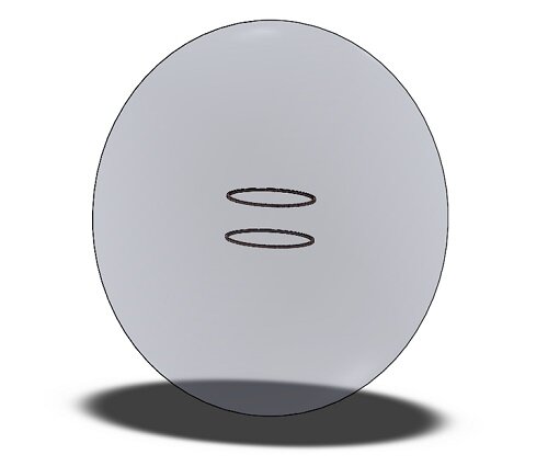
Figure 4- 3D model: an air region enclosing the coil of Helmholtz
Symmetry conditions were applied, allowing for the simulation of only one-quarter of the entire model. This strategy significantly reduced the solution time while maintaining solution accuracy.
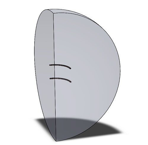
Figure 5- simulated model
Numerical Simulation and Results
AC simulation
Load restraint
In this study, two coils (Helmholtz coil) are defined as per Table 2.
Table 2 – AC Coils information
| Coil | AC current | Phase shift (degree) |
| Coil 1 | 7.3 A Peak value | 0 |
| Coil 2 | 7.3 A Peak value | 0 |
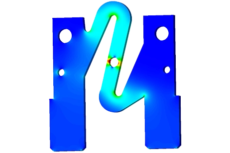
To apply symmetry conditions in the model, you need to use a tangential flux on the faces where symmetry is desired.
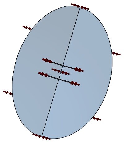
Figure 6- faces where applied tangential flux
Meshing
Figure 7 displays the mesh applied to the Helmholtz coil, a crucial step in FEA simulations. EMS calculates an element size based on the model's volume, surface area, and geometric details, affecting the mesh's size (nodes and elements). Mesh size depends on geometry, element size, tolerance, and control. In early analysis stages, larger elements offer faster results, while smaller ones improve accuracy. Mesh controls (listed in Table 4) adjust mesh size based on body dimensions and result importance.
Table 4 - Mesh controls applied for this model
| Name | Mesh Size (mm) | Bodies/ components |
| Mesh control 1 | 5.00 | Coils |
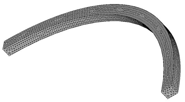
Figure 7- Meshed coil
ElectroMagnetic results
The AC Magnetic solver in EMS calculates various parameters, including flux density (B), field intensity (H), and total current density (applied + induced). Additionally, it generates a results table with circuit parameters such as inductance, resistance, and losses.
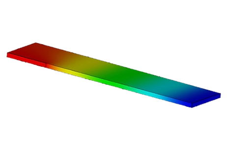
Figure 8 displays the Bz flux density along the coil axis, consistent with reference [1], page 55. Numerical simulation and experimental results [1] confirm the uniformity of flux density along the coil axis, as expected in Helmholtz coils.
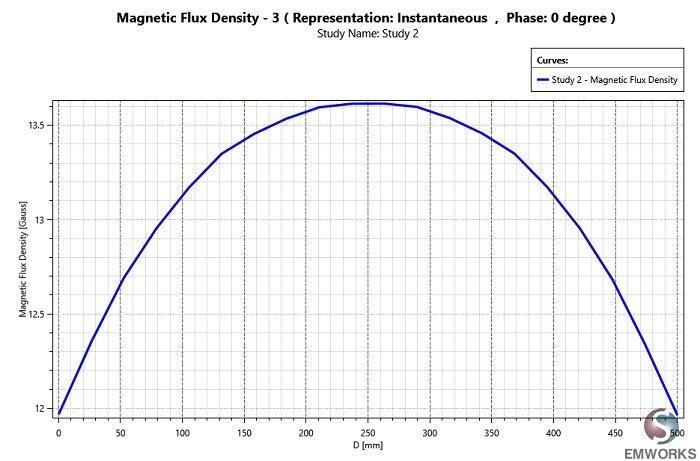
Figure 8- Bz along z axis
DC simulation
Apart from AC, Helmholtz coils can be powered by DC sources, necessitating magnetostatic simulations. Magnetostatic analysis, also known as DC Magnetic Field analysis, falls within the low-frequency electromagnetic domain. This analysis disregards displacement currents, operates in a time-independent manner, and assumes that objects are significantly smaller than the wavelength.
Magnetostatic analysis, whether linear or non-linear, computes magnetic fields generated by:
-
Permanent magnets.
-
Steady DC electric currents.
Load restraint
In the same tree, create a new study (Magnetostatic study).
Table 5 - DC coils information
| Coil | DC current |
| Coil 1 | 4.8 A |
| Coil 2 | 4.8 A |
ElectroMagnetic results
The Magnetostatic analysis enables the generation of flux density, magnetic field intensity, applied current, force density, and the computation of circuit parameters.
Figure 11 displays Bz along the z-axis of the Helmholtz coil, aligning with the findings in reference [1]. The flux density exhibits uniformity around the coil's center.
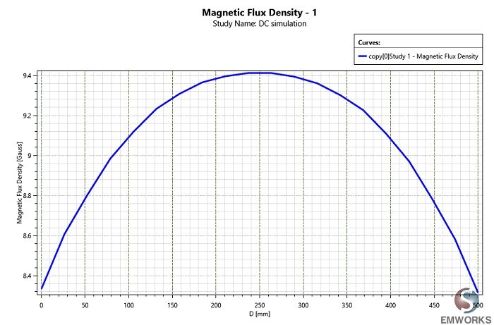
Figure 9 - Bz along z axis with DC current
Conclusion
The Helmholtz coil, a configuration of two aligned solenoid electromagnets, creates a nearly uniform magnetic field, crucial for various applications. It enables both the generation and cancellation of external magnetic fields, including the Earth's. In the realm of plant and seed research, these coils are indispensable, facilitating bioelectric experiments by providing a large, uniform magnetic field ideal for biomagnetic studies. The coil's design accommodates the treatment of 200 seeds simultaneously, operating with both AC and DC currents for versatility in experimental setups. Through comprehensive numerical simulations, we explored the electromagnetic behavior of Helmholtz coils, including AC and DC scenarios, validating our findings against experimental results. The detailed analysis covered parameters like flux density, field intensity, and current distribution, offering insights into the coil's performance under various conditions.
References
[1]:” DESIGN AND CONSTRUCTION OF HELMHOLTZ COIL FOR BIOMAGNETIC STUDIES ON SOYBEAN “by Dr SHASHI RAJ GYAWALI , the Faculty of the Graduate School at the University of Missouri-Columbia