Physics
A cylindrical region contains a homogenous, time-varying magnetic field $$
\vec{B} = B_0 \cos(\omega t) \, \hat{a}_z
$$
; B0 is the field magnitude and $$
\hat{a}_z \, \vec{}
$$
is vertical unit vector. Since there is no electric charge in the system, the changing magnetic field is the sole cause of the electric field $$
\vec{E}
$$
. According to Farady's equation :
$$
\nabla \times \vec{E} = - \frac{\partial \vec{B}}{\partial t}
$$
(eq.1)
or in the case where $$
\vec{B}
$$
only has z component:
$$
\frac{1}{r} \left( \begin{array}{c}
\frac{\partial}{\partial r} \left( r E_{\phi} \right) - \frac{\partial E_r}{\partial \phi}
\end{array} \right) \hat{a}_z = \omega B_0 \sin(\omega t) \hat{a}_z
$$
(eq.2)
where r and $$
\phi
$$
represent radial and angular coordinates of the cylindrical coordinate system (Fig. 1).
Due to the symmetry of the problem, its analysis can be simplified by noting that $$
E_r
$$
does not depend on $$
\phi
$$
, i.e. $$
\frac{\partial E_r}{\partial \phi} = 0
$$
. Equation 2 therefore, takes the following form:
$$
\frac{1}{r} \frac{\partial}{\partial r} \left( r E_{\phi} \right) = \omega B_0 \sin(\omega t)
$$
(eq.3)
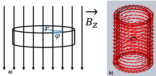
Figure 1 - a) Copper disc in vertical magnetic field;b) Changing magnetic field is produced inside a cylinder wrapped in coils that carry AC current;
To solve for r1∂r∂(rEϕ)=ωB0sin(ωt)
, equation 3 is multiplied by ρE
and then integrated from 0 to ρ=1
as:
which leads to
$$
E_{\phi} = \frac{1}{2} \omega B_0 r \sin(\omega t)
$$
If a copper disc is placed inside the cylinder, as a consequence of the induced electric field, eddy currents are distributed inside the disc. Current density j=21ωσB0rsin(ωt)a^ϕ
is, according to the Ohm’s law :
$$
\mathbf{j} \, \overset{\rightarrow}{=} \sigma \mathbf{E} \, \overset{\rightarrow}{=} \frac{1}{2} \omega \sigma B_0 r \sin(\omega t) \, \hat{a}_\phi
$$
where j=→σE=→21ωσB0rsin(ωt)a^ϕ
is specific conductivity of copper (σ=5.7×10⁷mS ). For a magnetic field with a magnitude of B0=1.58×10⁻²T
and angular frequency ω=2π⋅60rad/s
, magnitude of current density is j=r×1.69759×10⁸m3A
. Induced eddy currents lag the change in flux density by 90º.
Model
Eddy current distribution in a copper disc can be easily simulated in EMS as a AC Magnetic ![]() study. To create a uniform magnetic field inside the cylinder, allow a certain thickness to its wall so that you can define the wall as a wound coil. A cylinder with inner radius of 15mm and height of 50mm, should be used to define a Wound Coil with 100 turns and RMS current magnitude per turn of $$
study. To create a uniform magnetic field inside the cylinder, allow a certain thickness to its wall so that you can define the wall as a wound coil. A cylinder with inner radius of 15mm and height of 50mm, should be used to define a Wound Coil with 100 turns and RMS current magnitude per turn of $$
\dfrac{10}{\sqrt{2}}
$$
.For the Current phase select 0º - this will produce a cosine current profile in the coil. This current will in turn induce a relatively uniform flux density of magnitude $$
B_0 = 1.46 \times 10^{-3} \, \text{T}
$$
over the volume of the copper disc (radius: 3mm), placed in the center of the cylinder. To help magnetic field align vertically inside the cylinder, add Normal Flux boundary conditions to cylinder caps and Tangential Flux boundary condition to the inner face of the cylinder wall.
Boundary conditions
- In the EMS manger tree right-click on the Load/Restraint
 folder and select Normal Flux
  .
. - Click inside the Faces for Normal Flux box
 then select Cylinder caps .
 - Click OK
 .
.
- In the EMS manger tree right-click on the Load/Restraint
 folder and select Tangential Flux
 .
. - Click inside the Faces for Tangential Flux
 box then select the inner face of the Cylinder wall .
 - Click OK
 .
.
Coils
Eddy Effects
Meshing
To get a high resolution of current density results in the copper disc, a Mesh control of 0.1 mm should be applied to the copper disc.
To do so,
In the EMS manger tree right-click on the Mesh
 folder and select Apply Mesh Control
  .
.Click inside the Bodies
 box then select the inner face of the copper disc .
 Under Control Parameters click inside the Element Size
 box and type 0.1 mm.
Click OK
 .
.
To mesh the model:
In the EMS manger tree, right-click on the Mesh
 icon and select Create Mesh
  .
.Click OK
 .
.
Results
To plot the current density distribution in the copper disc, right-click the Current Density![]() in the EMS tree and select 2D Plot
in the EMS tree and select 2D Plot ![]() . For the current density Representation select Real (instantaneous). Maximum current density occurs for 90º (minimum at 270º ), since the eddy currents have sinusoidal time dependence (in the case of a cosine coil current and magnetic field).It is enough to select only 2 points along the disc radius – one in the center and the other one by the periphery. Type in the number of points you want in between and EMS will plot the current density along the disc radius.
. For the current density Representation select Real (instantaneous). Maximum current density occurs for 90º (minimum at 270º ), since the eddy currents have sinusoidal time dependence (in the case of a cosine coil current and magnetic field).It is enough to select only 2 points along the disc radius – one in the center and the other one by the periphery. Type in the number of points you want in between and EMS will plot the current density along the disc radius.
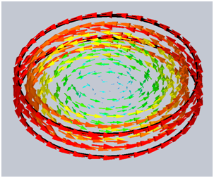
Figure 2 - 3D vector plot of Eddy current density inside the copper disc
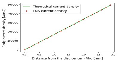
Figure 3 - Comparison of EMS and theoretical results for eddy current density