Physics of Capacitors
If the plate’s surface is much greater than the distance between them ($$
S \gg d^2
$$
), then the capacitor’s electric field can be regarded as homogenous and normal to the plates. In that case, the field outside the capacitor is nearly zero, while the field intensity inside the capacitor receives equal contributions from both electrodes:$$
e^{+} + e^{-}
$$
; $$
e^{+} = e^{-}
$$
(Figure 1). It's important to note that the force acting on each electrode is directly proportional to the charge it holds and the component of the electric field generated by the other electrode. For instance, the force on the positive plate is calculated as:
F^{+} = Q^{+} e^{-} = \frac{Q e}{2}
$$
(eq.1)
E = \frac{U}{d}
$$
. From equation 1 and the formula for capacitance of an air capacitor $$
C = \frac{\epsilon_0 S}{d}
$$
, the force acting on the capacitor plate can be expressed as:
F = Q \frac{U}{2d} = \frac{\epsilon_0 S U^2}{2 d^2}
$$
(eq.2)
where $$
\epsilon_0
$$
is the permittivity of space. For plates with dimensions of 100 mm*100 mm at a distance d= 2 mm and a Voltage amplitude of 10 V force magnitude is: $$
F = 1.104 \times 10^{-6} \, \text{N}
$$
.
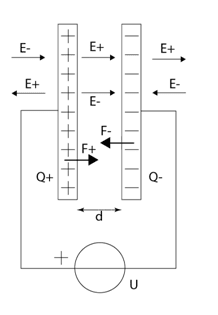
Figure 1 - Parallel plate capacitor connected to a voltage
Model
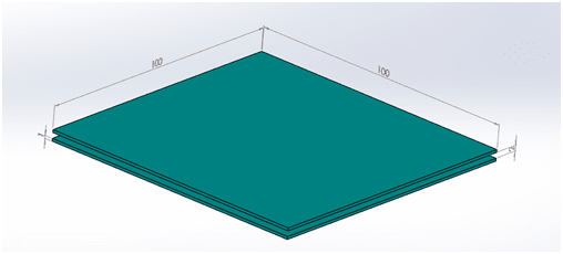
Figure 2 - CAD model of capacitor
Boundary Conditions
In order to consider the potential difference, a Fixed Voltage boundary condition is applied to both electrodes. To accomplish this,
- In the EMS manger tree, Right-click on the Load/Restraint
 folder.
 - Select Fixed Voltage
 .
. - Click inside the Bodies Selection
 box and then select the first plate of the capacitor.
 - Type 0 in the Voltage box.
- Click OK
 .
.
For the second plate:
- In the EMS manger tree, Right-click on the Load/Restraint
 folder.
 - Select Fixed Voltage
 .
. - Click inside the Bodies Selection
 box and then select the second plate of the capacitor.
 - Type 10 in the Voltage box.
- Click OK
 .
.
Results
The 3D Electric Field Property Manager Page appears.
2. In the Section Clipping tab, select the plane for section clipping in which you want to inspect the field intensity.
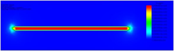
Figure 3 - EMS results for electric field intensity
E=d/U=5kV/m
As anticipated, the force predominantly exists on the z-axis, which is perpendicular to the plates (Figure 4). Its intensity aligns closely with the analytical estimate, deviating by only 3%.
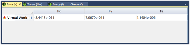
Figure 4 - EMS results for force on the plate
Conclusion
In conclusion, this application note provides a comprehensive understanding of the physics underlying capacitors, focusing on the relationship between electrode charge, electric field strength, and resulting forces. By examining theoretical principles and conducting practical simulations, valuable insights into capacitor behavior have been gained. The note highlights that when the surface area of capacitor plates significantly exceeds the distance between them, the electric field can be considered uniform and normal to the plates, with minimal field intensity outside the capacitor. Through detailed analyses and equations, the note demonstrates the direct proportionality between the force acting on each electrode and its charge, as well as the component of the electric field generated by the other electrode. Utilizing CAD modeling and EMS Electrostatic study, simulations accurately depict the electric field distribution and force magnitude within capacitors. These simulations confirm the theoretical predictions, showcasing the uniformity of the electric field inside the capacitor and the accuracy of force calculations.