Induction Heating
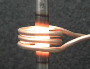
Induction heating is a highly efficient method used across various industries for processes like welding, brazing, and hardening. Its fast heating rate and low energy consumption make it superior to other heating methods. Induction brazing, for instance, employs electromagnetic fields to melt filler metals, surpassing traditional gas-based methods in efficiency and safety. Our study focuses on analyzing the induction brazing process for joining copper workpieces. Using Multiphysics FEM analysis, we conduct electromagnetic and thermal simulations to study temperature distribution during brazing.
Multiphysics Analysis
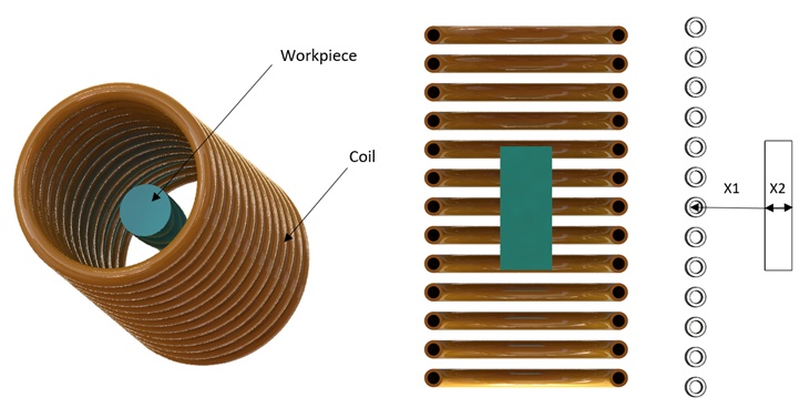
Utilizing the frequency domain of EMS coupled with the thermal module, we conducted heat transfer analysis within a defined region encompassing the metal workpieces. The 3D model, depicted in Figure 2, comprises an inductor coil with 13 turns encircling a cylindrical copper workpiece. For simplicity, the workpiece is represented as a single cylindrical bar, excluding the filler zone. Temperature and current results are calculated along lines X1 and X2.
| Part | Dimensions (cm) | |
| Coil | Coil diameter | 6 |
| Wire diameter | 0.6 | |
| Height | 11 | |
| Number of turns | 13 | |
| Workpiece | Diameter | 1.68 |
| Height | 4 | |
Both the coil and the workpiece are fabricated from copper material. Table 1 outlines the geometrical properties of the workpiece and inductor coil, while Table 2 provides the thermal and electrical properties of the copper utilized in the Multiphysics simulation.
| Material | Density (Kg/m²) |
Magnetic permeability | Electrical conductivity (S/m) |
Thermal conductivity (W/m.K) |
Specific heat capacity (J/Kg.K) |
| Copper (Cu) | 8900 | 0.99 | 6 E+07 | 385 | 390 |
Boundary conditions
1- Electromagnetic input:
The copper inductor is configured as a solid coil, capable of accommodating a peak current input of 300A at a frequency of 75 kHz.
2- Thermal input
Thermal convection is implemented on the surrounding air body at an ambient temperature of 22°C, with a heat transfer coefficient set to 10 W/m²°C.
Mesh
Figure 3 displays a 2D view of the mesh model, with a fine mesh control applied to both the coil and workpiece to improve result accuracy.
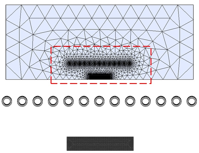
Figure 3 - The 2D view of the meshed model
Results
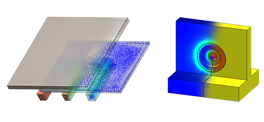
This section presents the Multiphysics simulation results achieved after one second of heating. The magnetic field distribution across the model is depicted by a 2D cross-sectional plot, as shown in Figure 4.
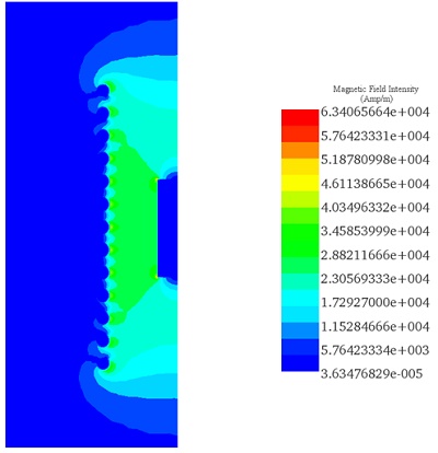
Figure 5 illustrates a 2D plot depicting the magnetic field intensity along line X1. It is evident from the graph that the maximum magnetic field values occur in the region between the external surface of the workpiece and the internal surface of the coil.
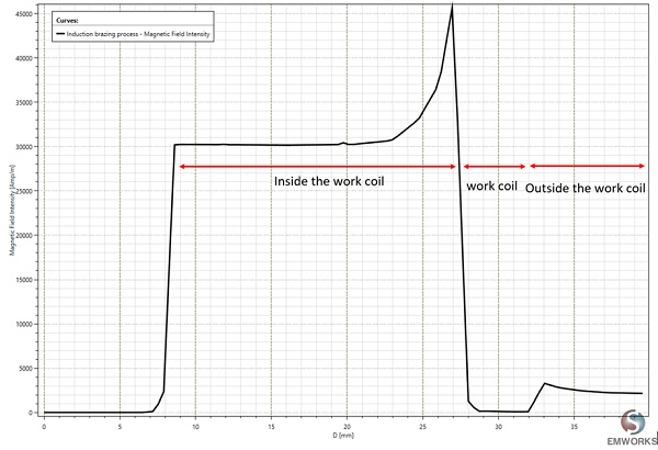
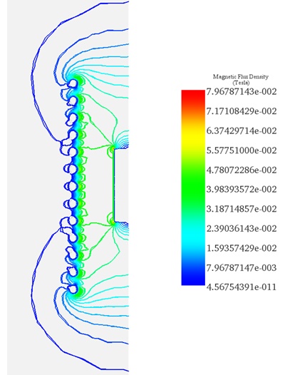
Figure 6 displays a line plot distribution showcasing the generated magnetic flux, reaching a maximum value of 7.96E-2 Tesla at the edges of the heated workpiece.
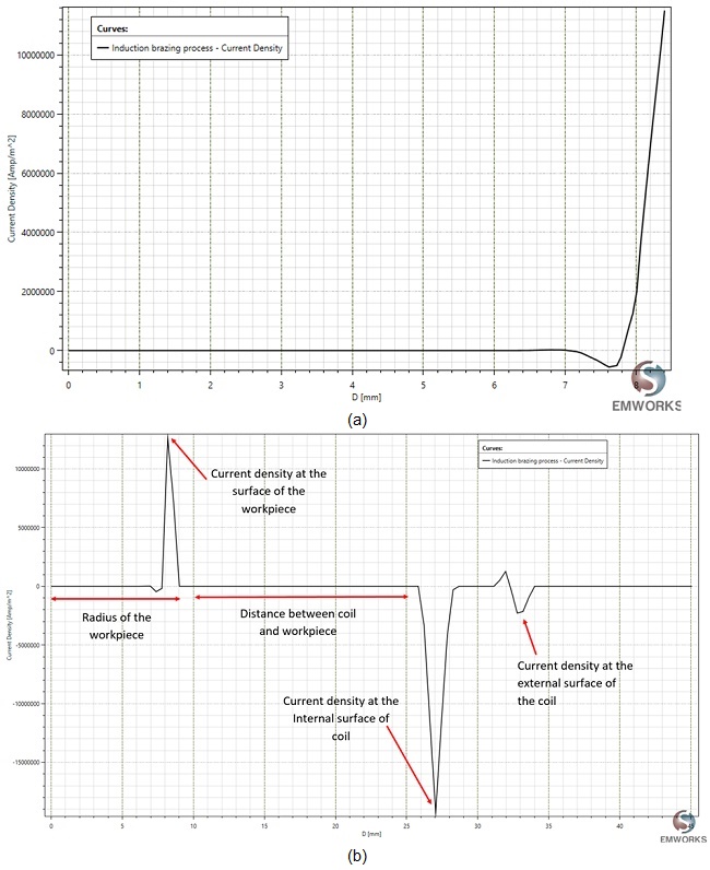
The induced eddy current is concentrated at the external lateral surface of the copper bar. Figures 7. a) and 7. b) depict the current density distribution for an excitation of 300A along lines X1 and X2, respectively.
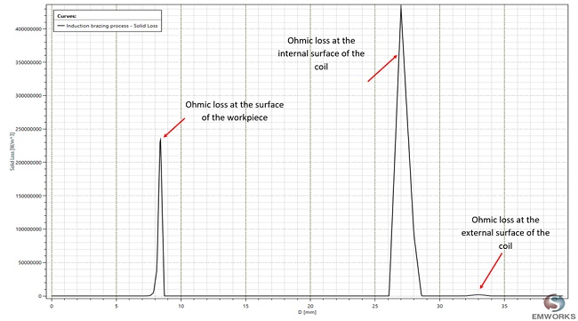
The ohmic loss results arising from the induced currents are illustrated in the 2D plot of Figure 8 along the X1 line. Power losses peak at 94W under ambient conditions of 22°C and a frequency of 75kHz. These ohmic losses are converted into heat, thereby raising the temperature of the workpiece.
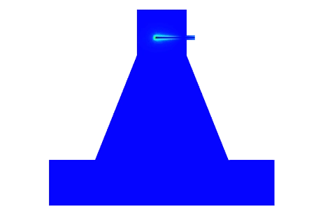
Due to the skin effect, the workpiece experiences higher current density on the surface facing the coil. Over one second, as the ohmic losses persist, the workpiece temperature gradually rises from the initial 22°C to a maximum of 28.24°C, as depicted in Figure 9. However, the workpiece temperature is non-uniform, fluctuating between 26°C and 28.2°C due to non-uniform current distributions.
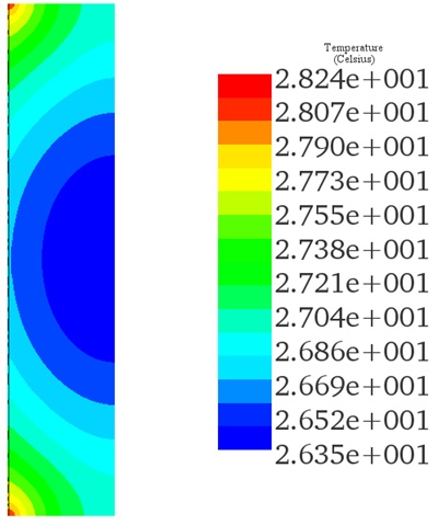
Figure 9 - Temperature distribution
Conclusion
The application note explores the efficacy of induction heating, particularly in brazing applications, through Multiphysics FEM analysis. Induction heating, renowned for its efficiency and rapid heating capabilities, is vital across various industries. The study specifically delves into the induction brazing process for joining copper workpieces, employing electromagnetic and thermal simulations to analyze temperature distribution during brazing. Through detailed modeling and simulation, the study showcases the magnetic field distribution, magnetic flux density, current density, and ohmic losses within the workpiece. Results indicate a non-uniform temperature distribution due to the skin effect, with temperatures gradually rising from the initial 22°C to a maximum of 28.24°C over one second of heating. Despite fluctuations, induced eddy currents concentrate at the external surface of the copper bar, leading to efficient brazing. Overall, the analysis provides valuable insights into optimizing induction brazing processes, emphasizing the importance of FEM simulations in understanding and enhancing induction heating applications for industrial processes.
References
[1] http://www.efd-induction.com/en/Applications/Brazing.aspx
[2] https://vacaero.com/information-resources/vacuum-brazing-with-dan-kay/1463-induction-brazing-vs-vacuum-brazing.html
[3] Khazaal, M. H., & Abdulbaqi, I. M. (2016, May). Modeling, design and analysis of an induction heating coil for brazing process using FEM. In Multidisciplinary in IT and Communication Science and Applications (AIC-MITCSA), Al-Sadeq International Conference on (pp. 1-6). IEEE.
-Techniques.webp)