Crosslinked Polyethylene
Crosslinked Polyethylene (XLPE) is a popular choice for insulating power cables due to its excellent electrical properties and thermal stability, particularly in high-voltage transmission. However, its durability is challenged by various stresses during service, potentially leading to functional failure. Thermal stress, driven by conductor Joule losses and aggravated by high current loads, can alter XLPE's dielectric properties. To mitigate this, accurate temperature rise prediction is essential in cable design. This study employs FEM simulations with EMS to investigate the thermal behavior of an XLPE power cable, considering its standard components: conductor, isolator, semiconductor layers, metallic ground conductor, and external PVC insulation.
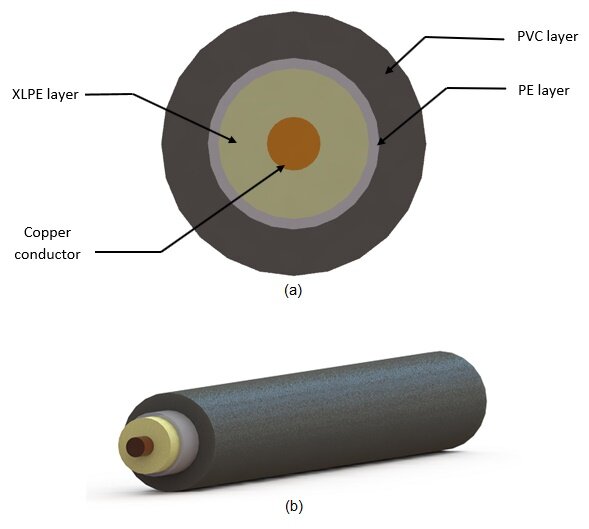
![Standard configuration of XLPE power cable [1].](https://lh7-us.googleusercontent.com/owb9NTis4q7L4R9WUh5Fq5nwdyAXYtUkf8o6Cn5Mx9DLSLTXXqjovPY4aVYoYVYzPwCM0_X6sPAB1hkJP7krcCYxwNI8-ZrMDKpFmXptP-IJufotluLJf6mTcxs4f-C_AMieYxff4pe4ZcU__Cq8zJ0)
CAD Model
The frequency domain AC module coupled with thermal analysis enables the examination of heat transfer across the XLPE Power Cable. Power losses determined from electromagnetic field analysis serve as input data for thermal analysis, predicting temperature rise in various cable-layers.
The simplified 3D model cable consists of four distinct regions, as depicted in Figure 2: an internal copper conductor surrounded by a thick XLPE layer, a thin Polyethylene (PE) layer, and an external PVC protective layer.
| Component | Dimensions |
| Conductor diameter | 23 mm |
| XLPE outer diameter | 64.6 mm |
| PE outer diameter | 73.6 mm |
| PVC outer diameter | 113.6 mm |
| Cable Length | 1 m |
The table below defines the corresponding material properties mentioned above.
| Material | Density () | Magnetic permeability | Electrical conductivity (S/m) | Thermal conductivity (W/m.K) | Specific heat capacity (J/Kg.K) |
| Copper (Cu) | 8900 | 0.99 | 6 E+07 | 385 | 390 |
| XLPE | 920 | 1 | 0 | 0.28 | 2174 |
| PE | 952 | 1 | 0 | 0.28 | 1796 |
| PVC | 1290 | 1 | 0 | 1 | 1600 |
Boundary conditions
1-Electromagnetic input:
The copper conductor is configured as a solid coil, capable of accommodating a current input range spanning from 300 to 1600 A peak at a frequency of 50 Hz.
2-Thermal input:
A ground temperature of 305K (32°C) is applied to the external PVC layer of the cable.
Thermal convection is applied on the air body surrounding the model at an ambient temperature of 305°K with a heat transfer coefficient set to 10 W/m².K.
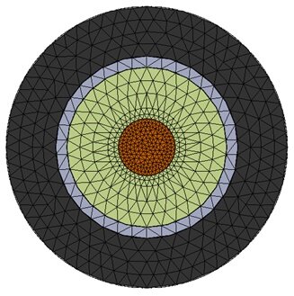
Mesh
Figure 3 displays the cross-sectional view of the meshed model. A fine mesh control is strategically applied to the heated sections, particularly focusing on the conductor, to ensure precise temperature results.
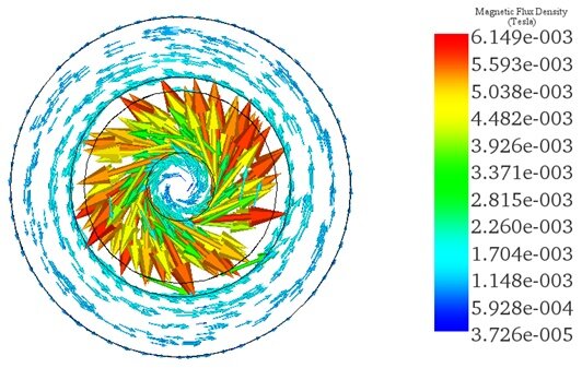
Results
To assess the XLPE power cable's thermal performance under varying loading currents, a series of simulations were conducted, ranging from 300A to 1600A, to determine the maximum operating temperature. Figure 4 illustrates the magnetic flux density across the cable's cross-sectional view, reaching a peak value of 6.15E-3 Tesla at 300A input.t.
The temperature peaks at 306.3K with a 300A current input, validating the findings from Reference [1] for the 2D model. The thermal distribution is depicted in the figure below.
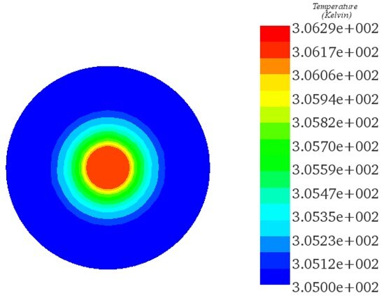
The maximum operating temperatures, obtained from EMS simulation for various tested current inputs, are showcased in a 2D plot variation across the cable radius. As the conductor surface serves as the primary heat source, the temperature remains at its peak along the conductor surface, gradually decreasing towards the ground temperature across the insulation layers.
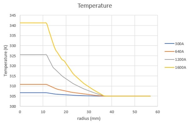
Figure 6 - Plot of the temperature variation versus current inputs across the cable radius.
A comparison between the thermal results from Reference [1] for the 2D model of the power cable and the EMS simulations for the 3D cable model reveals a strong agreement between the two.
| Results | 300A | 640A | 1200A | 1600A |
| 3D model-EMS | 306.3K | 310.9K | 325.75K | 341.23K |
| 2D model-Reference [1] | 306.03K | 309.89K | 321.9K | 335K |
Conclusion
The application note delves into the thermal behavior of Crosslinked Polyethylene (XLPE) power cables, crucial for high-voltage transmission systems. Through Finite Element Method (FEM) simulations with EMS, the study investigates temperature rise prediction, considering various stress factors like conductor Joule losses and external thermal conditions. A detailed 3D model of the cable, including its standard components, enables precise analysis of heat transfer. Simulation results reveal temperature distribution across the cable under different current loads, highlighting the significance of accurate thermal modeling in cable design. The study validates its findings by comparing EMS simulations with previous 2D model results, demonstrating a strong agreement. Ultimately, the research underscores the importance of understanding XLPE cable thermal behavior for ensuring operational reliability and longevity in power transmission applications, providing valuable insights for cable designers and engineers in optimizing cable designs to withstand operational stresses effectively.
Reference
[1]. Boukezzi, L., Y. Saadi, and A. Boubakeur. "The radial distribution of temperature in XLPE cable: An analysis with the Finite Volume Numerical Method (FVM)." Electrical Insulation and Dielectric Phenomena (CEIDP), 2010 Annual Report Conference on. IEEE, 2010.