Power insulators
Insulators support and isolate electrical conductors, preventing current flow. Used in cables or equipment, they're called insulation. Specifically, insulators support power lines on poles or towers, preventing current flow to the ground.
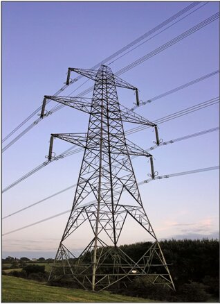 Figure 1 - Overhead power line in Gloucestershire, England. |
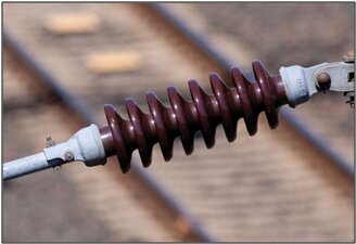 Figure 2 - Ceramic insulator used on electrified railways |
CAD Model
The EMS electrostatic analysis module is utilized for examining 3D models of electrode devices and power-line insulators in power applications. In this example, we focus on a power-line pole featuring a three-phase insulation setup. The central-phase line operates at 80 kV rms (138.56 kV rms phase-to-phase), while the upper and lower lines operate at 40 kV rms. The model comprises aluminum conductor lines and copper clamps connecting the conductors to silicon rubber and fiberglass insulators, which link to the tower. The electrostatic module computes the electric field and displacement field under these conditions. Results are visualized in both full 3D plots and 2D plots, including the electric field along a segment passing through air and silicon rubber insulator.
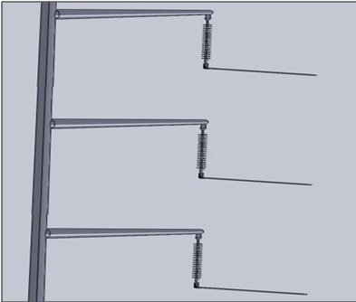
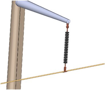
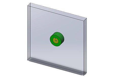
Figure 3 - Power line with Three-phase insulation scheme Figure 4 - Close-up view of the middle-phase insulator
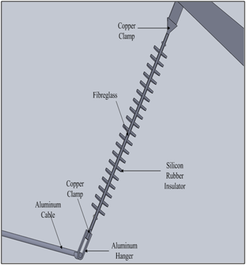
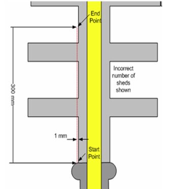
Figure 5- Close-up view of the middle-phase insulator. Figure 6 - Section view of the middle-phase insulator
with fiberglass and silicon rubber components
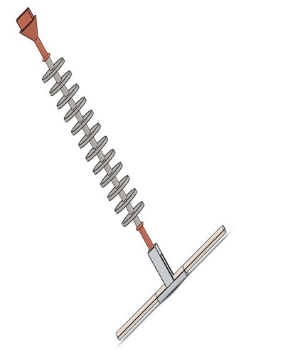
Figure 7 - 3D Model of insulator
The Study
In the EMS Electrostatic analysis, essential material properties include relative permittivity and dielectric strength, as outlined in Table 1. These parameters are crucial for accurately simulating electric fields and determining the breakdown voltage of non-conductor materials.
| Components / Bodies | Material | Relative permittivity | Dielectric Strength |
| Contact 1 | Copper | 1 | None |
| Ground_ Contact | Copper | 1 | None |
| Conductor | Aluminum | 1 | None |
| Contact 2 | Copper | 1 | None |
| Insulator | Silicon Rubber | 4 | 25.00e+006 V/m |
| Fibre | Fibreglass | 5.5 | 60.00e+006 V/m |
| Hanger | Aluminum | 1 | None |
| Inner_Air | Air | 1 | 3.00e+006 V/m |
| Outer_Air | Air | 1 | 3.00e+006 V/m |
Results
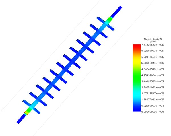
Figure 8 - Electric Field in the insulator and the fiber (fringe plot)
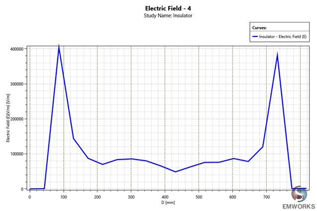
Figure 9 - Evolution of the Electric Field between two points located at the extremity of the fiber
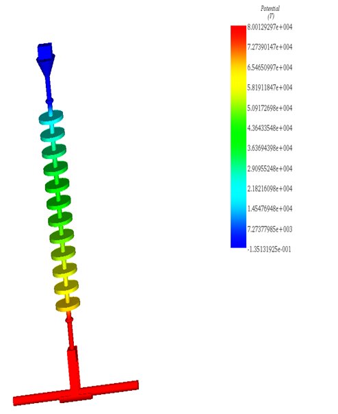
Figure 10 - Potential in the whole model
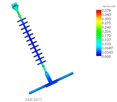
Figure 11 - Safety Factor
As illustrated in Figure 11, the peak value recorded is 0.378, indicating that our model does not experience any breakdown voltage.
Conclusion
The application note explores the role of power insulators in supporting and isolating electrical conductors to prevent current flow. Through electrostatic analysis using EMS, a 3D model of a power-line pole with a three-phase insulation setup is examined. The model consists of aluminum conductor lines and copper clamps connected to silicon rubber and fiberglass insulators. EMS computes electric fields and displacement fields, visualized through 3D and 2D plots. Key material properties like relative permittivity and dielectric strength are essential for accurate simulation. Results showcase the electric field distribution, potential distribution, and safety factor, indicating the absence of breakdown voltage. This thorough analysis aids in understanding insulator behavior and optimizing power distribution systems for efficiency and safety.
References
[1] https://en.wikipedia.org/wiki/Insulator_(electricity)