Submarine Power Cables
Submarine power cables transmit electricity underwater, serving both saltwater and freshwater environments, such as linking islands in the St. Lawrence River. Designed for high-voltage transmission, these cables consist of copper or aluminum conductors, insulation, and protective layers. Typically, conductors are up to 1200 mm^2, with larger sizes for over 12 kV applications. To safeguard against damage, cables are buried up to 1 meter deep in the seabed, although depths may reach 10 meters in certain conditions. Figures 1 and 2 show a 3-phase submarine cable cross-section and a standard system setup, respectively.
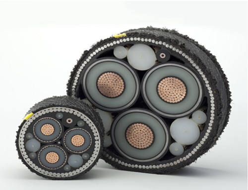
Figure 1 - cross-section of a 3-phase submarine cable
CAD model of 3-phase submarine cable
The 3D model depicted in Figure 3 was developed using CAD software. For the simulation of the submarine cable's functionality in a real-life setting, the scenario was set with the cable buried 1.0 m beneath the seabed surface, under the assumption of nonmagnetic soil conditions. Figure 4 illustrates this simulation setup. The dimensions of the simulated cable, detailed in Table 1, match those of an actual cable as referenced in [2].
Table 1 - Dimensions of the submarine cable
| Thickness (mm) | Diameter (mm) | Note | |
| Conductor (Copper) | 29.8 | ||
| Insulator (XLPE) | 17.3 | 64.4 | Outer diameter |
| Sheath (Lead) | 2.3 | 69.0 | Outer diameter |
| Armour (Steel wire) | 5.0 | 172.8 | Outer diameter |
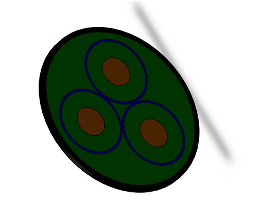
Figure 2 - 3D model of a 3 phase submarine cable
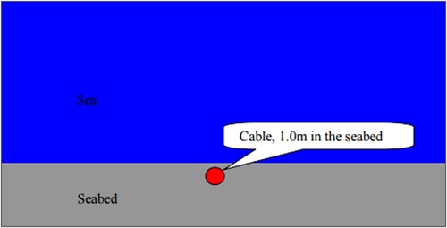
Figure 3 - Cabling scenario of the subsea cable used in the simulation
Figure 5 depicts a simplified model, highlighting the materials within the subsea cable components, with their electromagnetic properties detailed in Table 2. Operating at 50 Hz with 135kV AC voltage between phases, this high-power cable's simulation focuses on electric field calculations using the EMS AC Electric solver.
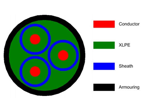
Figure 4 - Geometrical model of the submarine cable for simulation
| Relative Permittivity | Conductivity (S/m) | |
| Conductor (Copper) | 1.0 | 58,000,000 |
| Insulator (XLPE) | 2.3 | 0.0 |
| Sheath (Lead) | 1.0 | 1,000,000 |
| Armour (Steel wire) | 1.0 | 1,100,00 |
| Sea bed | 25 | 0.25 |
Simulation Inputs and Results
EMS' AC Electric Analysis studies conduction currents induced by time-varying electric fields, providing essential outputs like Electric Field (V/m), Displacement Field (C/m^2), Current Density (Amps/m^2), Potential (Volts), Energy (Joules), Resistance (Ohms), and Capacitance (Farads).
The solver excels in computing electric fields resulting from sinusoidal voltage or current variations. In this context, it's important to note that each core in the three-phase cable (phases 1, 2, and 3) maintains a 120° phase shift, with an applied AC Voltage magnitude of 135kV at a 50 Hz operating frequency.
Table 3 - Applied voltages
| Conductors | AC Voltage (kV) | Phase shift (degree) |
| Core 1 | 135 | 0 |
| Core 2 | 135 | 120 |
| Core 3 | 135 | 240 |
Meshing
Figure 5 displays the mesh of a 3-phase cable, a pivotal aspect in FEA simulations. EMS calculates an optimal global element size for the model, considering its volume, surface area, and geometric intricacies. The generated mesh size (nodes and elements) hinges on various factors, including model geometry, element size, mesh tolerance, and control settings. During preliminary design analysis for quicker results, a larger element size may be selected. Conversely, for precision, a smaller element size may be necessary. Mesh control allows us to fine-tune the mesh size for each body based on its dimensions and significance in the results, as detailed in Table 4.
Table 4 - Mesh controls applied for this model
| Name | Mesh Size (mm) | Bodies/ components |
| Mesh control 1 | 5.00 | Conductors/Insulator/ Sheath / Armour |
| Mesh control 2 | 1.75 | Faces of conductors/ insulator/ Sheath/ Armour |
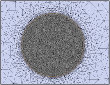
Figure 5- Meshed model of three- phase cable.
Electric Results
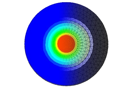
As previously mentioned, the AC Electric solver provides current and E-field distributions, along with potential differences. Figures 6 and 7 depict the electric field distribution within all cable cores. Due to metallic sheaths acting as grounded shields, the E-fields remain confined within each core, displaying a radially symmetric distribution within the dielectric XLPE. Consequently, no E-field escapes from the cores, resulting in a zero E-field outside the submarine cable. The maximum electric field (E) occurs at the conductor surface, measuring approximately 1.0969e+7 V/m (similar to [1]). Figure 8 displays the electric potential within the submarine cable.
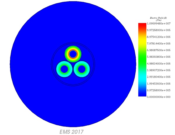
Figure 7 - E field animation versus phase, vector plot
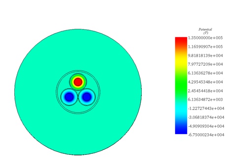
Figure 8 - Electric potential
Conclusion
The application note delves into the design and simulation of submarine power cables, crucial for transmitting electricity underwater in various environments. These high-voltage cables, consisting of conductors, insulation, and protective layers, are essential for connecting islands and facilitating power distribution. Through detailed CAD models and electromagnetic simulations, the study explores the functionality and performance of these cables in real-life scenarios. Results from HFWorks simulations demonstrate accurate resonance frequencies and quality factors, validating the effectiveness of the design. Additionally, insights into the electric field distribution within the cable cores offer valuable understanding for optimizing performance and ensuring efficient power transmission.
References
[1]: https://en.wikipedia.org/wiki/Submarine_power_cable
[2]: “Electromagnetic Simulations of 135 kV Three-Phase Submarine Power Cables” by Dr Yi Huang, Department of Electrical Engineering & Electronics Liverpool, L69 3GJ UK retrieved from the following URL - https://corporate.vattenfall.se/globalassets/sverige/om-vattenfall/om-oss/var-verksamhet/vindkraft/kriegers-flak/14-mkb-bilaga-414-cmacs-electrom.pdf