A Collinear Antenna
A collinear antenna array consists of dipole elements aligned in parallel and collinear fashion. This configuration yields improved gain and directivity in the E-plane. Theoretically, doubling the number of dipole elements should double the gain, but in practice, losses often limit this gain increase. In this simulation example, we explore a collinear array operating at 3.2 GHz using HFWorks.
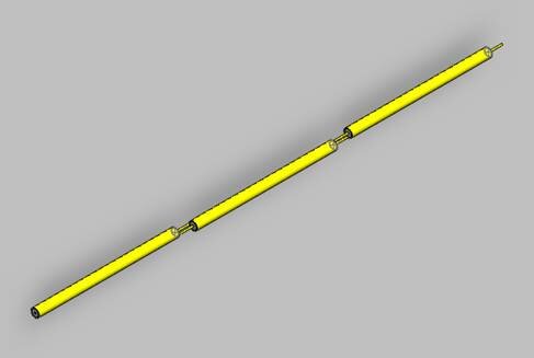
Figure 1 - The antenna array
The antenna structure employs Franklin's principle, combining multiple radiating dipoles to aggregate radiation intensities effectively. By incorporating a 180° phase shift between the dipoles to avoid destructive interference, this antenna design can also be adapted to accommodate different types of dipole antennas, such as microstrip patch antennas.
Dimensions
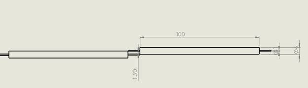
All dimensions in this schematic are in millimeters. Please note that the diagram depicts the connection between two of the three dipoles, with the second link constructed in the same manner as the first.
Solids and Materials
The antenna's feed is situated on the lateral face of one of its ends, while the other end functions as an open circuit. Each dipole is modeled as an insulating layer of Duroid 5880 substrate with perfect electric conductor (PEC) inner and outer conductor layers. All dipoles are enclosed within an air box, and its lateral surfaces serve to simulate an anechoic chamber.
Meshing
In this example, it's crucial to ensure that the meshing is accurate on the circularly formed dipoles so that the simulator accurately represents their circular shape.
Results
Once the meshing is complete, we proceed to run an antenna simulation in the frequency range from 0.5 GHz to 3.5 GHz. This allows us to precisely visualize the antenna's behavior around the intended frequency.
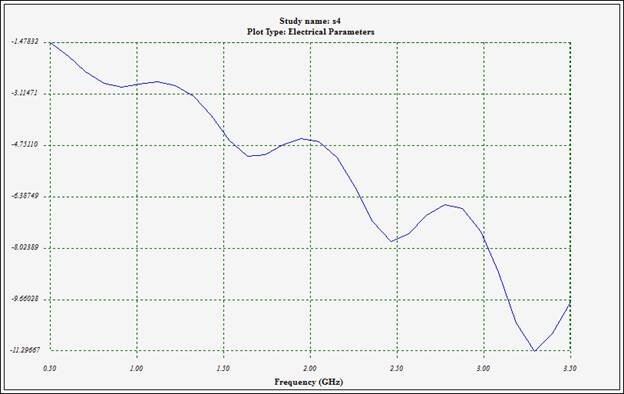
Figure 3 - Reflection coefficient at port 1
As indicated in the previous section on dimensions, the full wavelength corresponds to approximately 100 millimeters, which aligns with a frequency of around 3 GHz. Based on the graph above, we have achieved a favorable level of return loss at 3.25 GHz. The curve continues to decrease, reaching an acceptable match and demonstrating the constructive sum principle of the three radiating dipoles. A figure depicting the radiated total field is provided below.
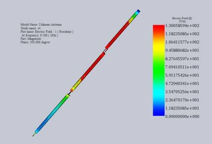
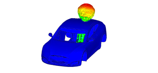
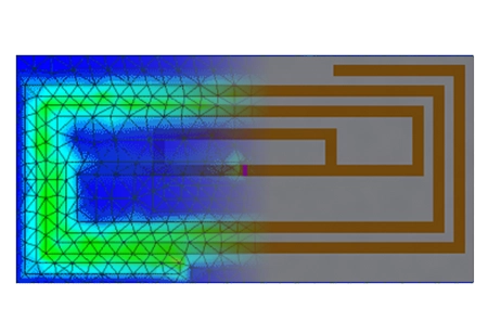
Figure 4 - Near electric field distribution
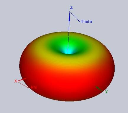
Figure 5 - Far-field distribution
To obtain smoother plots in both 2D and 3D, we can refine the angles' steps during the creation of the study. In the figure below, the 3D radiation of the electric field is plotted for a clearer visualization.
Conclusion
The application note presents a detailed examination of a collinear antenna array operating at 3.2 GHz, showcasing the application of Franklin's principle to enhance gain and directivity by aligning dipole elements in a parallel and collinear manner. Despite theoretical expectations of doubling the gain with each addition of dipole elements, practical limitations due to losses often temper these gains. Employing HFWorks for simulation, the study demonstrates effective radiation intensity aggregation through a 180° phase shift between dipoles, mitigating destructive interference. The construction utilizes Duroid 5880 substrate for dipoles, enclosed in an air box simulating an anechoic chamber, with meticulous attention to mesh accuracy for circular dipoles. The simulations, spanning a frequency range from 0.5 GHz to 3.5 GHz, underline a favorable return loss at 3.25 GHz, validating the antenna's design efficiency and its capability to achieve intended performance metrics, as evidenced by the reflection coefficient and field distribution analyses. This insight underscores the antenna's potential in applications requiring enhanced directivity and gain.