A Car FM Antenna
Listening to FM radio while driving is a universally enjoyed experience. However, it's important to note that the FM broadcast band varies by region. In Europe and Africa (ITU region 1), it spans from 87.5 to 108.0 megahertz (MHz), while in America (ITU region 2), it covers 88.0 to 108.0 MHz. In Japan, the range is from 76.0 to 90 MHz. Eastern Europe used the OIRT band, ranging from 65.8 to 74.0 MHz, but many countries in this region have transitioned to the 87.5 to 108 MHz band, similar to Russia. This study focuses on the design and simulation of a car antenna that operates effectively within all these frequency bands, assessing its performance and capabilities.

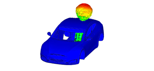
Figure 1 - FM radio antenna's radiation above a car
Simulation
In this simulation, our goal is to gain insights into the emission and reception capabilities of the car antenna design and its compatibility with multiple FM broadcast bands. To achieve this, we employ a fast sweep frequency plan, allowing the simulator to efficiently estimate the antenna parameters across the desired frequency ranges.
Load/ Restraint
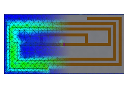
The positioning of the car antenna, whether it's inside or outside the vehicle, and its relative orientation with respect to the Base Transceiver Station (BTS), are crucial factors that influence its performance. To accurately simulate these conditions, we apply a port to the small surface of the Duroid 5880 material. Similar to a coaxial cable, we treat the outer surface as a Perfect Electric Conductor (PEC), while the antenna's stem is assigned a signal boundary condition to replicate its behavior.
Results
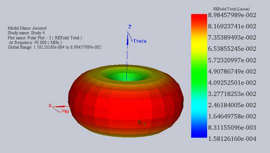
The electric field radiation pattern of the car antenna at 90 MHz is depicted in the figure below. This pattern closely resembles that of an omnidirectional antenna and remains consistent for all Phi angles, with Theta held constant. It's worth noting that using smaller angle steps, such as a 15° step for Phi and a 10° step for Theta, results in a smoother and more detailed plot.
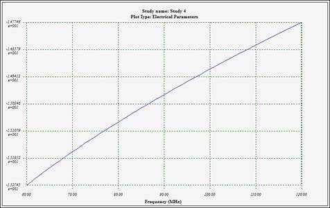
The return loss at the antenna's port falls within the range of approximately 15 dB from 60 MHz to 120 MHz. This level of return loss is considered acceptable and covers the FM frequency bands mentioned in the introduction.
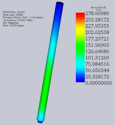
This figure displays the radiation pattern of the electric field at 90 MHz with a phase equal to Pi/2.
Conclusion
This application note explores the design and simulation of a car FM antenna tailored to operate efficiently across various FM broadcast bands globally, addressing the diverse frequency ranges from 87.5 to 108.0 MHz in Europe and Africa, 88.0 to 108.0 MHz in the Americas, and 76.0 to 90 MHz in Japan, with a note on the historical OIRT band in Eastern Europe. Through a comprehensive simulation process, the study aims to understand the antenna's emission and reception capabilities within these bands, employing a fast sweep frequency plan for effective parameter estimation. Key considerations include the antenna's placement relative to the vehicle and its orientation toward the Base Transceiver Station (BTS), simulating real-world conditions to enhance performance accuracy. The results demonstrate that the antenna exhibits an omnidirectional radiation pattern at 90 MHz, indicative of consistent performance across all required FM bands. With return loss levels within acceptable ranges, the study concludes that the designed car antenna meets the necessary specifications for global FM radio reception, ensuring a universally enjoyable listening experience for drivers worldwide.