A Helical Antenna
A Helical Antenna, comprised of a helix-shaped conductor wire, operates in two modes: normal and axial. In normal mode, it functions as an omnidirectional monopole due to its small dimensions relative to the wavelength. In axial mode, its dimensions approach the wavelength, making it directional. Designed with HFWorks for 2.45 GHz operation in axial mode, it utilizes a helix of alumina or copper wire, achieving circular polarization and over 8dBi gain, ideal for television and satellite communications to mitigate atmospheric losses.
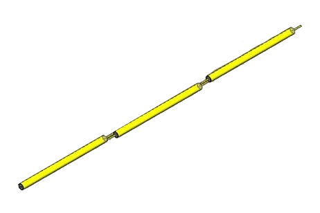
.jpg)
Figure 1 - Helical antenna model (3D SolidWorks view)
Simulation
To simulate the helix antenna's behavior, focusing on radiation patterns and parameters like gain and directivity, we'll establish an Antenna study across a specified frequency range (1.9 GHz to 2.3 GHz over 10 frequencies). This involves setting radiation boundaries to mimic an anechoic chamber, crucial for accurate simulation. HFWorks Antenna studies offer extensive plotting options and the ability to utilize electrical parameters from Scattering Parameters simulations, enhancing analysis capabilities.
Solids and Materials
The helix, crucial to the antenna's assembly and typically made from copper or aluminum, dictates the electric field's circular polarization due to its shape. For accurate simulation, the ground beneath the helix is modeled with a Perfect Electric Conductor (PEC) boundary condition, easily assigned through the material browser, ensuring it acts as the ground metal.?
Load/ Restraint
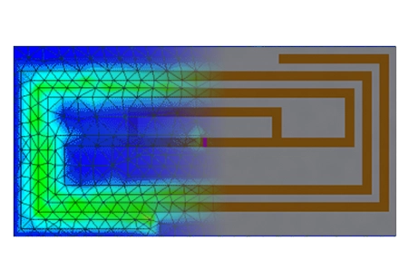
Radiation boundaries are defined to simulate the antenna in the open air, with the port set under the ground metal, akin to a coaxial cable connector. The helix extends to the port through a cylinder, where the outer cylinder is designated as PEC, and the inner part, containing the helix wire, is given a +Signal boundary. A Teflon material separates these boundaries within the cylinder's body, ensuring accurate simulation of electromagnetic properties.
Meshing
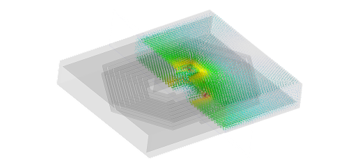
For effective simulation, the helical conductor's meshing is critical to solving Maxwell's equations accurately. Meshing should be detailed, especially for round shapes, to reflect the geometry accurately without overdoing it. Similarly, the Teflon cylinder carrying the signal wire requires fine meshing for precise results, balancing detail with computational efficiency.
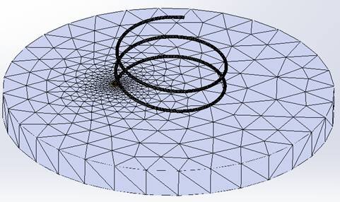
Figure 2 - Mesh of the helix antenna
Results
Antenna simulations offer various 3D and 2D plots to analyze different aspects of performance. For antennas, radiation pattern plots are particularly insightful, illustrating how the antenna distributes energy in space. These plots are essential for understanding the directional characteristics and efficiency of the antenna's design.
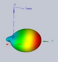
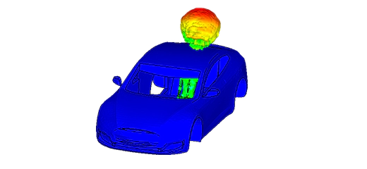
Figure 3 - 3D radiation pattern of an helix antenna
The figure illustrates the antenna's power radiation pattern variation with the Theta angle, offering both 2D and 3D conformal views. HFWorks also calculates Scattering Parameters for antenna studies, aiding in matching optimization. In this scenario, optimal matching for the antenna occurs at 2.47 GHz, demonstrating its capabilities for precise frequency targeting.
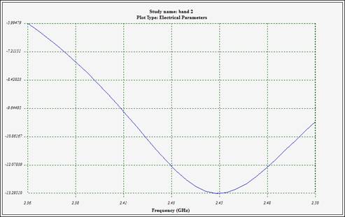
Figure 4 - Variations of reflection coefficient at the antenna's port
Polar plots for antenna parameters display a comprehensive range of metrics, including the radiated electric field, radiation intensity, directivity, gain pattern, and axial ratio, among others. The capability to simulate, plot, and animate the electric field distribution along the antenna wire enhances understanding, with animations depicting the electric field's variation across the omega-t angle from 0 to 360° at 2.47 GHz. This approach provides a dynamic visualization of the antenna's performance characteristics at the specified frequency.
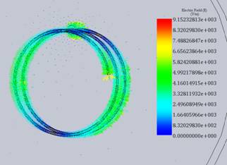
Figure 5 - Near electric field vector distribution at 2.45 GHz
Conclusion
This application note explores the design and simulation of a helical antenna tailored for 2.45 GHz operation, focusing on its use in axial mode to achieve circular polarization and a gain exceeding 8dBi. Such specifications make it particularly suited for television and satellite communications, where atmospheric loss mitigation is crucial. Utilizing HFWorks, the simulation encompasses an extensive frequency range to analyze radiation patterns, gain, and directivity, providing insights into the antenna's performance in an environment mimicking an anechoic chamber. The helix, made from materials like copper or aluminum, plays a pivotal role in achieving the desired electrical characteristics, supported by a perfectly electrically conductive ground. Detailed meshing strategies ensure the precision of simulations, critical for the helix's complex geometry. Results from the study, including radiation pattern variations and reflection coefficient analyses, underscore the antenna's effectiveness at its operational frequency, offering valuable data for optimizing television and satellite communication systems.