Magnetic Pulse Welding
Magnetic pulse welding (MPW) is a cutting-edge, high-speed forming method extensively employed in the aerospace and automotive sectors. Unlike explosion welding, MPW utilizes magnetic force instead of explosives to propel objects together swiftly.
In contrast to traditional welding methods, MPW avoids material melting, preserving original material properties. By leveraging magnetic force for acceleration, MPW achieves a solid-state weld without external heat, mitigating thermal distortions. Despite its benefits, MPW induces interfacial phenomena such as joule heating from eddy currents.
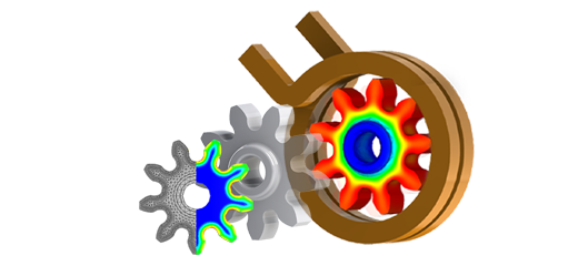
Figure 1 illustrates a typical example of two tubes joined through magnetic welding.
![Magnetic pulse welding sample [1]](/ckfinder/userfiles/images/Magnetic-pulse-welding-sample-%5B1%5D.png)
Figure 1 - Magnetic pulse welding sample [1]
CAD Model
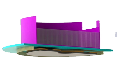
An electromagnetic simulation, coupled with thermal analysis, investigates the heating effect in the MPW welding process. This case study features a one-turn coil with a field shaper, demonstrating EMS's multi-physics capabilities in solving electromagnetic and thermal problems in the time domain via the EMS transient module. Figure 2 depicts the simulated model.
![3D model, dimensions [2] and schematic illustration of the MPW test case [3]](/ckfinder/userfiles/images/3D-model-dimensions-%5B2%5D-and-schematic-illustration-of-the-MPW-test-case-%5B3%5D.png)
Simulation Setup
Utilizing the Transient Magnetic module of EMS enables computation and visualization of time-varying magnetic fields, addressing phenomena like eddy currents, power losses, and magnetic forces. To conduct an analysis using EMS, follow these steps:
1. Material Application: Assign suitable materials to all solid bodies involved.
2. Electromagnetic Input: Specify the required parameters related to electromagnetic properties.
3. Thermal Input: Define thermal properties and input parameters as necessary.
4. Mesh Generation and Solver Execution: Create a mesh for the entire model and execute the solver to obtain results.
Materials
The tube and rod are both made from aluminum alloy AA2024-T351. Refer to Table 1 for an overview of their key electromagnetic, mechanical, and thermal properties. Understanding these properties is essential for accurate modeling and simulation, particularly in processes like electromagnetic simulation and thermal analysis.
| Material | Part | Density (Kg/m3) | Electrical conductivity (S/m) | Specific heat capacity (J/Kg.K) | Thermal conductivity (W/m.K) |
| Aluminum alloy 2024-T351 | Tube and Rod | 2700 | 1.74 $$ 10^7 $$ | 795 | 143 |
| Copper alloy | Field shaper | 7900 | 2.66 $$ \textstyle 10^7 $$ | 486 | 36 |
| Steel | Coil | 7800 | 4.06 \(10^7\) | 486 | 36 |
Thermal Input
The thermal convection inputs for the ambient air body are as follows:
- The initial temperature of the simulations is set to 298 K.
- The convection coefficient is set to 10 W/m²K.
Electromagnetic Input
In this study, a one-turn solid coil is defined as the current source.
![Input current waveform [2]](/ckfinder/userfiles/images/Input-current-waveform-%5B2%5D.png)
Figure 3 - Input current waveform [2]
Meshing
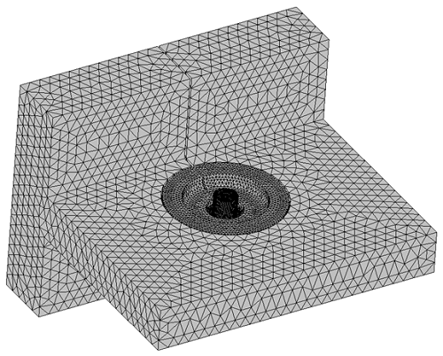
In meshing, EMS calculates an optimal element size considering the model's volume, surface area, and geometric intricacies. The resulting mesh, composed of nodes and elements, is influenced by factors like model geometry and mesh tolerance. Additionally, mesh quality can be enhanced using the Mesh Control feature. In this model, Mesh Control refines the meshing on the rod and tube components, ensuring accurate representation (refer to Figure 4).
Results
The numerical simulation yielded several results after half of the first impulse of the input current. Once the solution was completed, various outcomes were generated, including magnetic flux density, magnetic field intensity, eddy current, inductance, impedance, flux linkage, current, induced voltage, force, torque, and losses.
The magnetic flux density distribution notably demonstrates the shielding effect of the tube during diffusion, effectively blocking most of the magnetic field from penetrating inside the tube.
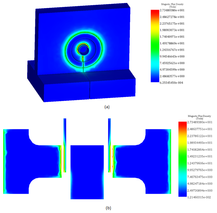
Figure 5 - Magnetic flux density distribution for the whole model a) Along the axial plane of the field shaper at the end of the first half cycle (11µs) b).
Figure 6 presents a comparison between the magnetic flux density results obtained through EMS simulation and those referenced in [3]. This comparison specifically examines the magnetic flux density on the external surface of the tube during the initial half period of the impulse current.
![Magnetic flux along the mid plane of the field shaper at the outside surface of the tube vs time for both Reference [3] and EMS results](/ckfinder/userfiles/images/Magnetic-flux-along-the-mid-plane-of-the-field-shaper-at-the-outside-surface-of-the-tube-vs-time-for-both-Reference-%5B3%5D-and-EMS-results.png)
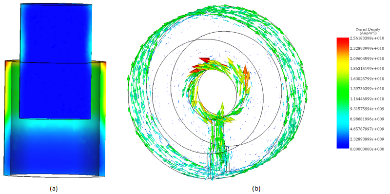
Figure 8 illustrates the temperature distribution for the tube during the initial half period of the impulse current. It highlights the specific region experiencing a sudden temperature increase during the collision.
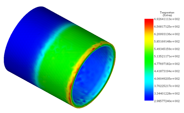
The table below presents a comparison of results between EMS and the reference [2] for the maximum values of temperature distribution in the tube part.
| Temperature (K) | EMS | Reference [2] |
| Tube | 692 | 698 |
Conclusion
Magnetic Pulse Welding (MPW) represents a revolutionary advancement in welding technology, particularly beneficial in aerospace and automotive industries for its high-speed, solid-state welding capabilities. Unlike traditional methods, MPW utilizes magnetic forces to join materials without melting them, preserving the original properties of the materials. This method ensures a weld with minimal thermal distortion due to the absence of external heat, although it introduces interfacial phenomena like joule heating from eddy currents.
The application of MPW in joining two tubes showcases its effectiveness in creating a strong weld while maintaining the integrity of the materials involved. Through electromagnetic simulation coupled with thermal analysis, the study investigates the heating effects during the MPW process, highlighting EMS's ability to address complex multi-physics problems. The simulation results, including magnetic flux density and temperature distribution, validate the process's efficiency. Notably, the comparison of EMS results with reference data confirms the simulation's accuracy in predicting the welding outcomes.
References
1]. Seungmin Tak , Hanbin Kang , Inseok Pack , Jinkyu Choi and Seoksoon Lee "Numerical Simulation of Magnetic Pulse Welding Process for Aluminum Tubes to Steel Bars" Proceedings of ICTACEM 2017 International Conference on Theoretical, Applied, Computational and Experimental Mechanics December 28-30, 2017, IIT Kharagpur, India
2]. T. Sapanathan, K. Yang, D. Chernikov, R.N. Raoelison, V. Gluschenkov, N. Buiron, M. Rachik, "Thermal Effect during Electromagnetic Pulse Welding Process", in: Materials Science Forum, Trans Tech Publ, (2017) 1662-1667.
3]. T. Sapanathan, K. Yang, R. Raoelison, N. Buiron, D. Jouaffre, and M. Rachik, “Effect of conductivity of the inner rod on the collision conditions during a magnetic pulse welding process,” in 7th International Conference on High Speed Forming, Dortmund, DOI 10.17877/DE290R-16981, 2016.