A Dipole Antenna
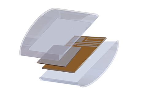
Dipole antennas find various RF applications. However, feeding them with a coaxial unbalanced line can pose challenges due to the dipole's balanced nature. Using coaxial cables can lead to common mode currents and radiation issues. To address this, a BALUN is typically employed. In this printed dipole antenna operating at 2.4 GHz, a BALUN integrated with a tapered line allows direct coaxial connection. The butterfly shape technique enhances bandwidth.
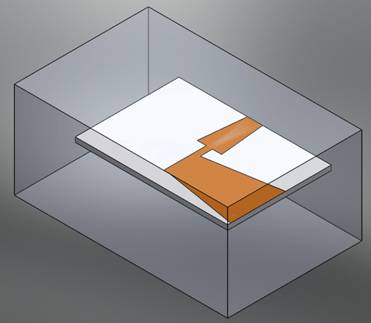
Figure 1 - Helical antenna model (3D SolidWorks view)
Simulation
To analyze the behavior of this dipole antenna, including radiation patterns, gain, and other antenna parameters, we will conduct an Antenna study covering a frequency range from 1.8 GHz to 3.8 GHz. In antenna simulations, radiation boundaries are crucial and are assigned to the outer air surfaces to mimic an anechoic chamber.
Solids and Materials
Load/ Restraint
Meshing
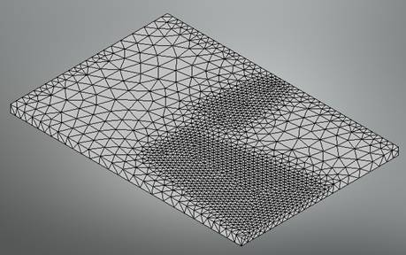
Figure 2 - Mesh of the dipole antenna
Results
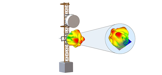
Various 3D and 2D plots are available for analysis. The following figure illustrates the radiation pattern of the antenna at 2.3 GHz:
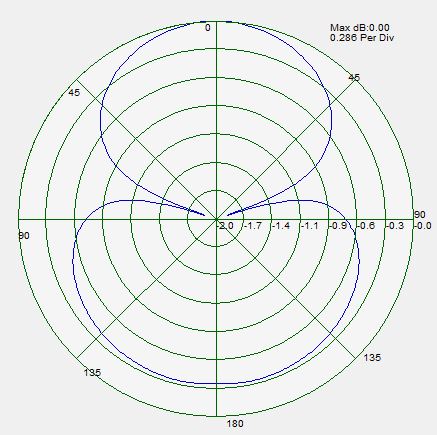
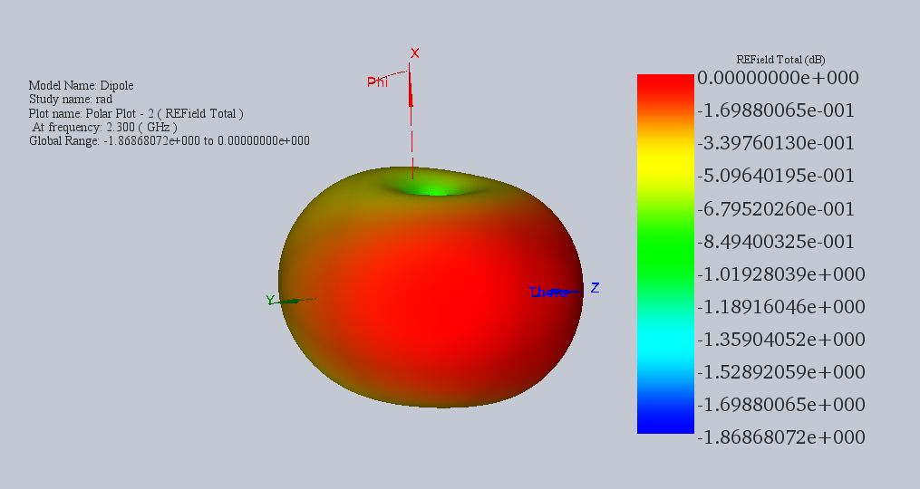
Figure 3 - 2D and 3D radiation patterns of the dipole antenna at 2.3 GHz
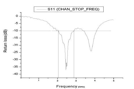
Figure 5 - Variations of the measured reflection coefficient at the antenna's port
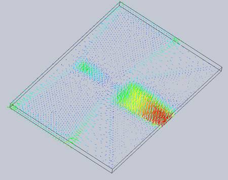
Figure 6 - Near Electric field vector distribution
Conclusion
The application note explores a printed dipole antenna operating at 2.4 GHz, addressing challenges associated with coaxial feeding due to the dipole's balanced nature. By integrating a BALUN with a tapered line, a direct coaxial connection becomes feasible, enhancing bandwidth through a butterfly-shaped technique. Simulation via HFWorks involves an Antenna study spanning 1.8 GHz to 3.8 GHz, considering radiation patterns, gain, and antenna parameters. Key elements include a Duroid 5880 substrate, Perfect Electric Conductor surfaces, and radiation boundaries to emulate an anechoic chamber. Precise meshing and analysis yield insights into radiation patterns and reflection coefficients. HFWorks facilitates visualization of electric field distribution and offers parameters like radiated electric field and gain pattern for comprehensive analysis, demonstrating the effectiveness of the printed dipole antenna in RF applications.