Single-phase transformer
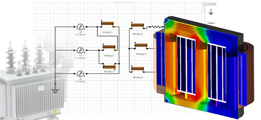
In this application note, we leverage EMS to analyze a single-phase transformer. The AC Magnetic module of EMS, combined with a thermal solver, is employed to calculate magnetic fields, electromagnetic losses (core loss, excess loss, hysteresis loss, eddy loss), and temperature changes in the transformer
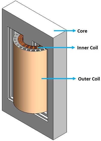
CAD model of a Single-phase transformer
The CAD model of a single-phase transformer comprises a core, an inner coil, and an outer coil, illustrated in Figure 1. The transformer core is constructed from M27 material.
Coupling to Thermal Analysis
Thermal analysis computes solid temperature distribution via conduction and manages heat flux at model boundaries using convection. In EMS, it seamlessly follows electromagnetic analysis, automatically pre-computing heat sources.
Material
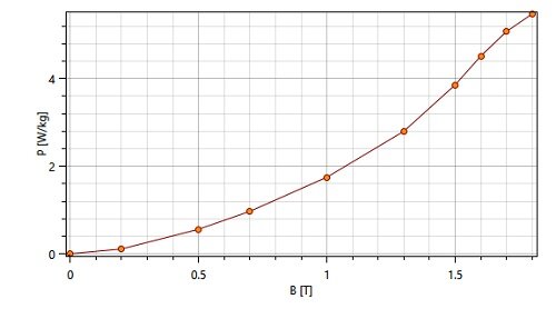
The simulated model includes a laminated steel core, inner coil, outer coil, and air. Material properties are listed in Table 1, and the coreloss PB curve is displayed in Figure 2.
| Component | Material | Relative permeability | Electrical Conductivity (S/m) | Thermal Conductivity (W*m-1 * k-1) |
| Core | laminated steel (M27 at 0.36mm; Mass density: 7650 kg/m^3) | Nonlinear | 2.32558 e+006 | 43 |
| Inner Coil/ Outer Coil | Copper | 0.99991 | 5.7e+007 | 401 |
| Coils Air, Inner Air, Outer Air | Air | 1 | 0 | 0.024 |
Primary/ secondary windings - Open circuit case
In this simulation, the inner and outer coils are represented as wound coils. The primary coil is driven by a current input of 10*300 A-turns, while the secondary side of the transformer features a 600-turn open-circuit winding. The simulation operates at a frequency of 60 Hz.
Thermal Inputs
Convection is the heat transfer mode involving heat exchange between a solid surface and a moving fluid (or gas). In EMS, convection boundary conditions are applied to all air bodies (Outer Air, Inner Air, and Coils Air). A convection coefficient of 10 W/(m²·K) and a bulk ambient temperature of 300 Kelvin were specified.
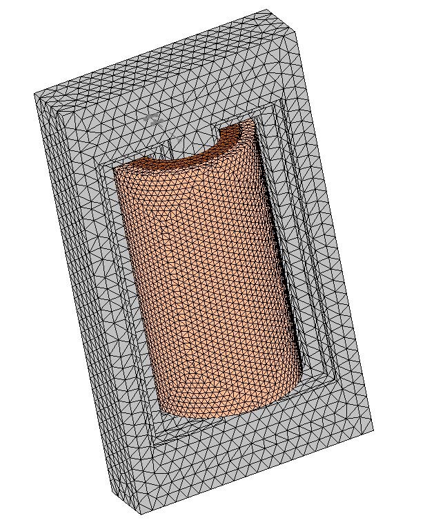
Mesh
For enhanced accuracy without expanding the mesh, apply mesh control to regions with expected significant variation. Refer to Figure 3 for the resulting mesh.
Simulation and results - Open circuit condition
EMS computes and provides various output data like magnetic fields, losses, currents, voltages, inductance, and resistance matrices for transformer design and optimization. Figure 4 displays the core's magnetic flux density, with peak fields at the middle leg reaching 2.1T. The side legs exhibit fluxes ranging from 1T to 1.7T, as shown in the cross-sectional view in Figure 5.
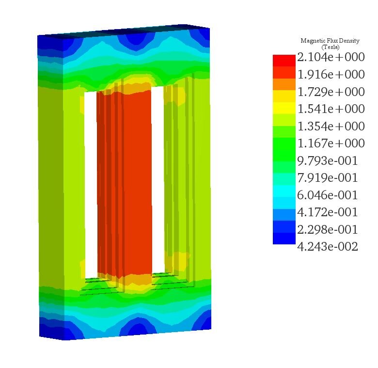
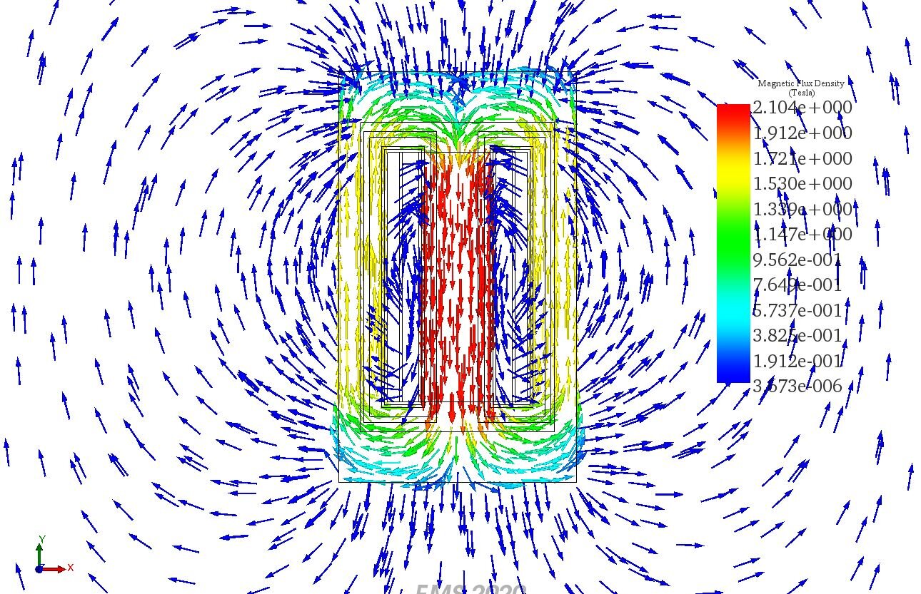
Figure 6 displays multiple cross-sectional plots of the H field, with the highest H field reaching approximately 3.24e+3 Amp/m in the middle leg of the transformer.
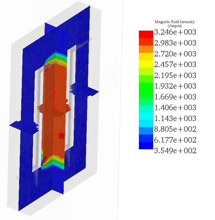
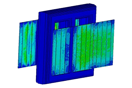
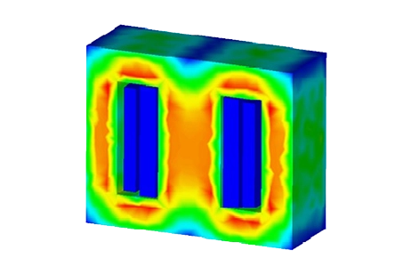
Figure 7 presents a plot of the density of the coreloss results, with the total coreloss being approximately 8.9 kW, attributed mainly to hysteresis and eddy losses. Heat generation in the transformer is caused by both iron and winding losses due to the Joule effect. In Figure 8, temperature results for the single-phase transformer are displayed. The maximum steady-state temperature reaches approximately 58°C, primarily due to coreloss. A cross-sectional view of the transformer reveals the temperature distribution within the transformer core, with the highest temperature occurring in the middle leg.
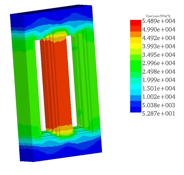
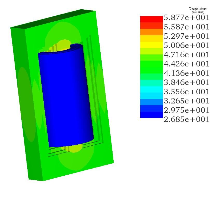
Figure 7 - Temperature results of the transformer
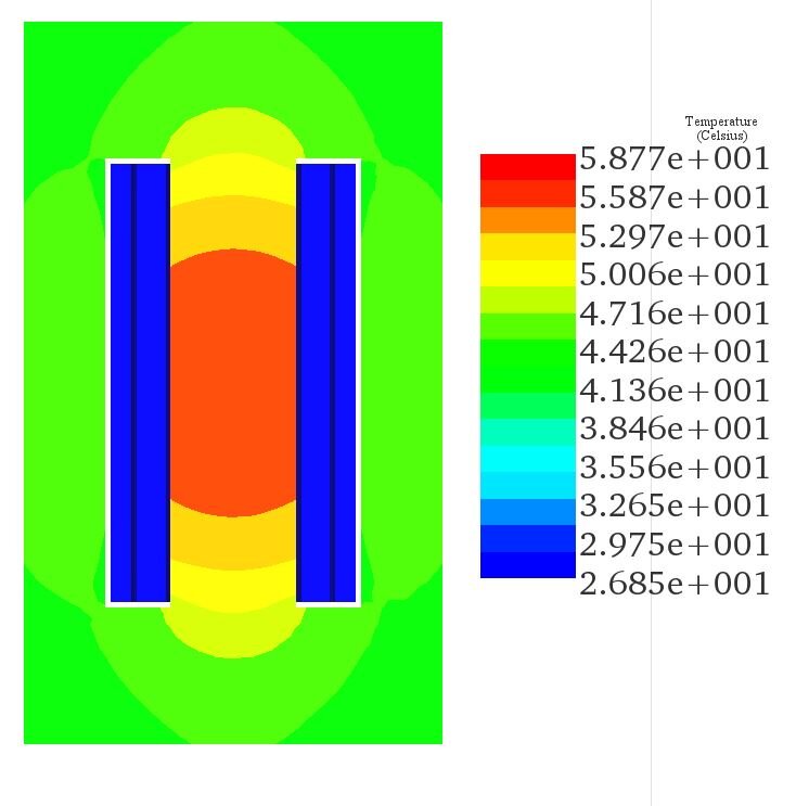
Figure 7 - Cross-section view of the temperature results
Conclusion
This application note provides a comprehensive analysis of a single-phase transformer using EMS, focusing on the AC Magnetic module combined with a thermal solver to evaluate magnetic fields, electromagnetic losses, and temperature variations. The single-phase transformer model includes a laminated steel core and copper coils, encapsulating the core's construction and material properties. Thermal analysis complements electromagnetic assessment by calculating temperature distribution and heat flux, emphasizing the seamless integration of these analyses in EMS.
Simulation results under open-circuit conditions at 60 Hz reveal detailed insights into the transformer's performance, including magnetic flux density, with peak fields observed in the transformer's core. The simulation also quantifies electromagnetic losses, highlighting hysteresis and eddy losses as primary contributors. The thermal outputs reveal the transformer's maximum steady-state temperature to be approximately 58°C, with core losses significantly impacting the temperature profile.