Description
This application note delves into the electrostatic field strength calculation within a dual-layer dielectric cylinder, featuring an inner layer with a 5mm radius (?r2 = 2) and an outer layer with a 10mm radius (?r1 = 5), all within a uniform transverse electrostatic field (E0 = E0x), as shown in Figure 1. The goal is to compare EMS results with previously published data [1] for validation purposes.
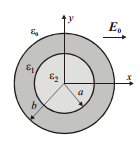
Figure 1: Two layers dielectric cylinder
Leveraging EMS's 3D capabilities, this study refines traditional 2D electrostatic models by considering both the cylinder's minimal depth and the surrounding air, enhancing accuracy in field simulation.
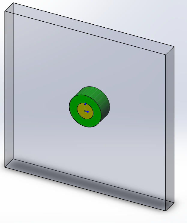
Figure 2: SolidWorks model of the dielectric cylinder
The Study
The EMS Electrostatic module calculates electric field strength and potential distribution in dielectric cylinders and surrounding air. To use it, create an Electrostatic study in EMS and follow three crucial steps: assign appropriate materials to all solid bodies, set necessary boundary conditions (Loads/Restraints), and mesh the entire model.
Materials
In this example, only three materials need to be applied, as detailed in Table 1.
|
Component/Body
|
Relative Permittivity
|
|
Air box
|
1.0
|
|
Inner cylinder
|
2.0
|
|
Outer cylinder
|
5.0
|
Table 1: Materials of all solid bodies in the Electrostatic study
Applying materials is simple: right-click on the component icon and select the desired material.
Loads/Restraints
Meshing
Meshing critically influences analysis accuracy in EMS, which auto-determines global element size considering the model's geometric specifics. Initial analyses may use larger elements for speed, while detailed studies require finer mesh for precision. This benchmark's uncomplicated geometry leads to a standard mesh with 10 mm elements and 0.01 mm tolerance. For enhanced accuracy in areas of significant field variation, such as dielectric cylinders, a 1 mm local mesh control is applied, as depicted in Figure 3..
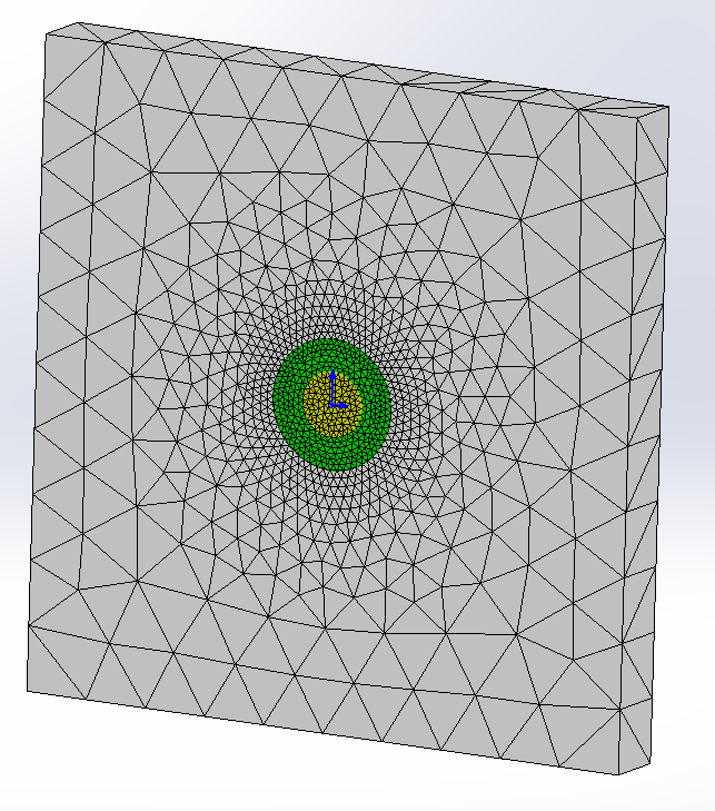
Figure 3: Mesh of the structure
Results
The Electrostatic module outputs include folders for the electric field (E), displacement (D), and potential (V), plus a table of electrostatic energy and capacitance. Visualization options range from fringe to contour plots, with functionalities for zooming and exporting.
This benchmark specifically compares the electric field fringe plot in cylinders and air against [1], using EMS line plots for precision at defined points. Figures 4-6 demonstrate EMS's alignment with published results.
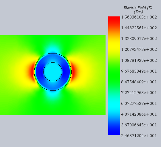
Figure 4: Electrostatic field distribution obtained by EMS
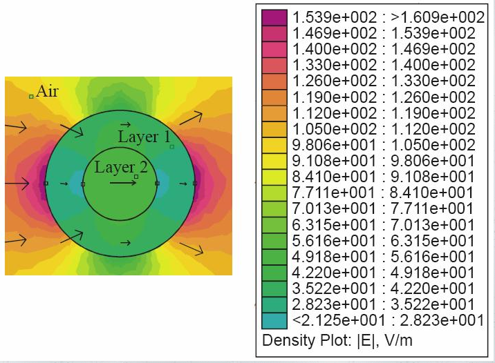
Figure 5: Electrostatic field distribution as reported in [1]
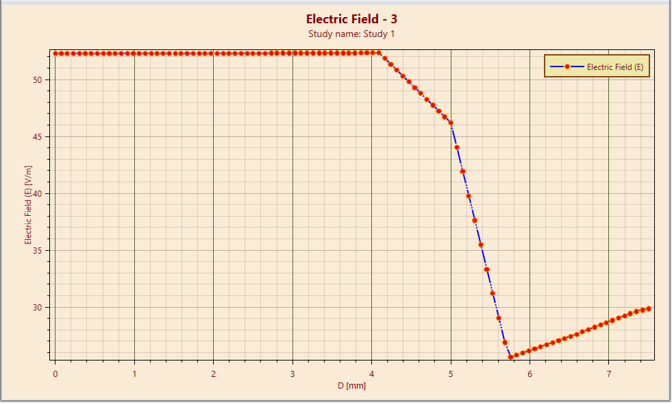
Figure 6: Line plot of electrostatic field between (0.0, 0.0) and (0.75cm, 0.0) obtained by EMS
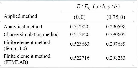
Table 2: Electrostatic field at (0.0, 0.0) and (0.75cm, 0.0) as reported in [1]
Conclusion
This application note presents a detailed study on calculating the electrostatic field strength within a dual-layer dielectric cylinder exposed to a uniform transverse electrostatic field using EMS's 3D simulation capabilities. The study aims to enhance traditional 2D models by incorporating the cylinder's depth and surrounding air, improving the accuracy of field simulations. The EMS Electrostatic module is utilized to compute the electric field strength and potential distribution in and around the dielectric cylinders, following a systematic process involving material assignment, boundary condition setup, and meshing. The study's boundary condition simulates an external electrostatic field with a 10V difference across a 100mm air gap. Results from the EMS simulation are compared against previously published data, showing close alignment in the electric field distribution within the cylinders and surrounding air. The application of EMS for this benchmark demonstrates its effectiveness in accurately simulating complex electrostatic fields in dielectric materials, validating its use against established research.
References
[1] Peric, M.T; Cvetkovic, Z.Z; Aleksic, S.R., "Two Layers Dielectric Cylinder in Homogeneous Field," Proceedings of the European Conference on Antennas and Propagation: EuCAP (ESA SP-626). 6-10 November 2006, Nice, France. Editors: H. Lacoste & L. Ouwehand. Published on CDROM, p.396.1