Spoke Motor
Electric motors, particularly spoke-type motors, are gaining traction in industrial applications due to their high efficiency, power factor, and versatility in speed. These motors feature a unique design with compact permanent magnets arranged in a spoke pattern, optimizing torque generation. Among permanent magnet motors, spoke types stand out for their superior torque density, assuming cost-effective production and efficient cooling. This application note details the analysis of a 24-slot/8-pole spoke-type motor's performance without load and under load, utilizing EMWORKS2D for simulation. A 2D model of this motor is depicted in Figure 1.
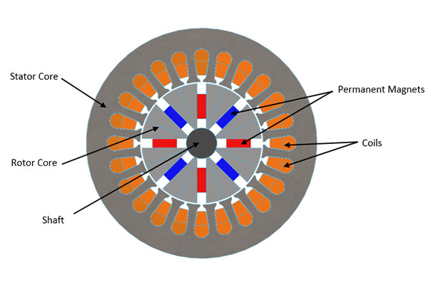
Figure 1 - a 2D cross section of the 24slot/8pole Spoke Type Motor.
Spoke Motor Settings
1- Materials Selection
Material selection significantly impacts the performance of spoke-type motors. Research indicates that neodymium iron boron is the optimal choice for magnets, provided they are adequately cooled, due to their superior properties. Table 1 showcases the materials chosen for the spoke motor being analyzed.
| Motor component | Material |
| Stator | AISI 1010 Steel |
| Rotor | AISI 1010 Steel |
| Magnets | NdFeB: N4212 |
2- Coercivity Direction for the Magnets
The coercivity directions of the spoke motor magnets are defined within local Cartesian coordinate systems, where the magnetization direction can be positive (for north magnets) or negative (for south magnets), as demonstrated in Figure 2.
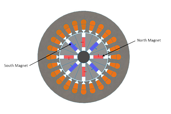
Figure 2 - Coercivity Direction of the Spoke Magnets.
3- Defined Rotor Angle
The rotor angle refers to the angle between the rotating rotor axis and the stationary stator axis, as depicted in Figure 3.
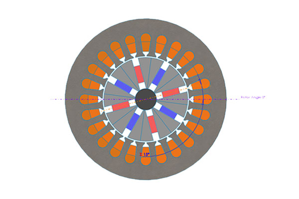
Figure 3 - Rotor Angle Definition.
4- Defined Winding Configuration
The spoke-type motor being analyzed features 24 double-layer slots with one parallel path, and each of its phases (A, B, and C) contains 30 turns. This 3-phase winding configuration is detailed in Figure 4.
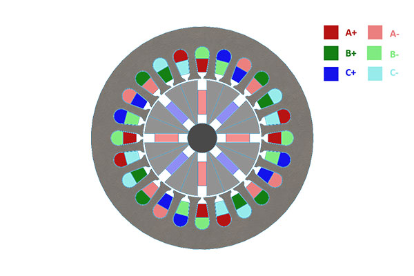
Figure 4 - Winding configuration for the spoke motor.
Simulation and results
1- No-Load analysis of the spoke-type motor
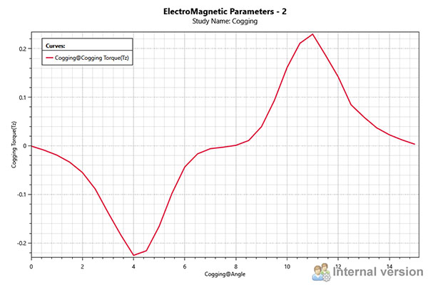
a- Cogging Torque of the Spoke Type Motor
The cogging torque of the spoke-type motor is simulated over one period with EMWORKS2D. The specifics of this study, including simulation properties, are outlined in Table 2, while the cogging torque's variation over time is depicted in Figure 5.
| Parameter | Value |
| Start Simulation Time (s) | 0 |
| End Simulation Time (s) | 0.03 |
| Step Simulation Time (s) | 0.001 |
| Angular Velocity (deg/s) | 500 |
| Initial Angle (deg) | 0 |
b- No Load Analysis of the Spoke Type Motor
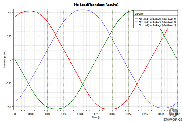
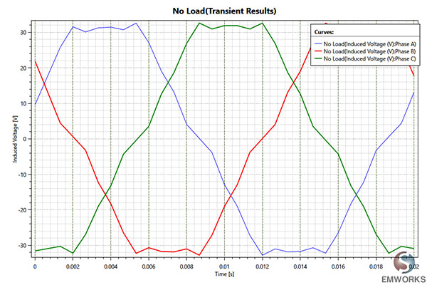
The no-load analysis of the spoke-type motor, conducted over one period using EMWORKS2D, details its properties in Table 3. The variation of the 3-phase winding linkage over time is shown in Figure 6, while the 3-phase induced voltage over time is depicted in Figure 7.
| Parameter | Value |
| Frequency (Hz) | 50 |
| Start Simulation Time (s) | 0 |
| End Simulation Time (s) | 0.02 |
| Step Simulation Time (s) | 0.00066667 |
| Angular Velocity (deg/s) | 4500 |
| Initial Angle (deg) | 0 |
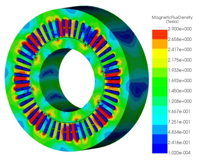
c- Magnetic field mappings of the Spoke Type Motor
The magnetic field mapping of the spoke-type motor, a key outcome from the no-load analysis, is illustrated at an initial angular position of 0 degrees in Figure 8.
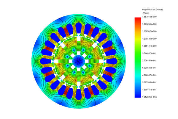
Figure 8 - Magnetic Field Mapping of the spoke-type motor under no load conditions, 0deg.
2- On-load analysis of the spoke-type motor
a- On Load Torque of the Spoke Type Motor
The spoke-type motor has been simulated under load conditions, with the applied 3-phase sinusoidal current described by equation (1). The parameters for the on-load study are detailed in Table 4.
$$ \begin{array}{l}
I_a = I_{\max} \times \sin\left( 2 \pi f \times \text{time} - T_{\text{shift}} \right) \\
I_a = I_{\max} \times \sin\left( 2 \pi f \times \text{time} - \frac{2 \pi}{3} - T_{\text{shift}} \right) \\
I_a = I_{\max} \times \sin\left( 2 \pi f \times \text{time} - \frac{4 \pi}{3} - T_{\text{shift}} \right)
\end{array} $$
| Parameter | Value |
| Frequency, f (Hz) | 50 |
| Max Current, $$ I_{\max} $$ (A) | 10 |
| Time Shift, $$ T_{\text{shift}} $$ (s) | 0.019 |
| Start Simulation Time (s) | 0 |
| End Simulation Time (s) | 0.04 |
| Step Simulation Time (s) | 0.0005 |
| Angular Velocity (deg/s) | 4500 |
| Initial Angle (deg) | 0 |
The resulting torque under load conditions versus time is depicted in Figure 9.
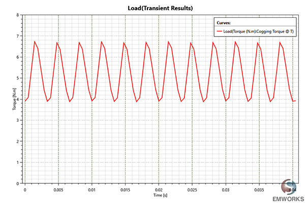
Figure 9 - On Load Torque versus Time of the spoke-type motor.
b- Core Loss Results
The core loss was investigated using the non-linear AISI 1010 Steel material for both rotor and stator cores, with the Steinmetz loss coefficient detailed in Table 5.
| Coefficient | Signification | Value |
| Kh | Hysteresis Loss Coeff. | 2020 |
| Kc | Eddy Current Loss Coeff. | 0.116 |
| Ke | Excess Loss Coeff. | 3.31 |
The total core loss for the spoke-type motor being analyzed over time is illustrated in Figure 10.
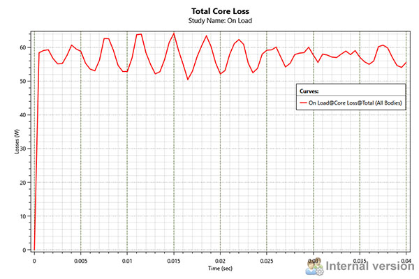
Figure 10 - Total Core Loss of the Spoke Motor versus Time.
c- Magnetic field mappings of the Spoke Type Motor
The magnetic field of the spoke motor, under load conditions and at an initial angular position of 0 degrees, is presented in Figure 11.
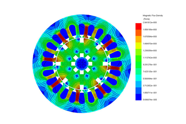
Figure 11 - Magnetic field mapping of the spoke-type motor under no load conditions.
Conclusion
The application note delves into the analysis of spoke-type motors, highlighting their rising popularity in industrial applications due to their efficiency and torque density. Specifically, it focuses on a 24-slot/8-pole spoke-type motor, detailing its performance characteristics both under no-load and on-load conditions through EMWORKS2D simulations. Notable aspects include the material selection for optimal performance, coercivity direction of magnets, rotor angle definition, and winding configuration. Results from the simulations provide insights into cogging torque, flux linkage, induced voltage, and magnetic field mappings, both with and without load. Additionally, the study examines core loss coefficients and total core loss over time. These analyses offer a comprehensive understanding of the spoke motor's behavior and performance metrics.
References
[1] Website, https://www.eurekamagazine.co.uk/design-engineering-features/technology/cooling-technology-in-this-electric-spoke-motor-makes-it-more-efficient-and-lightweight/176765/.