Magnetic Levitation
Magnetic levitation suspends objects in mid-air using magnetic fields, eliminating contact, wear, and friction. This boosts efficiency, cuts maintenance costs, and extends product lifespan. With broad applicability across industries, magnetic levitation technology has garnered global interest, leading to the development of numerous systems worldwide.
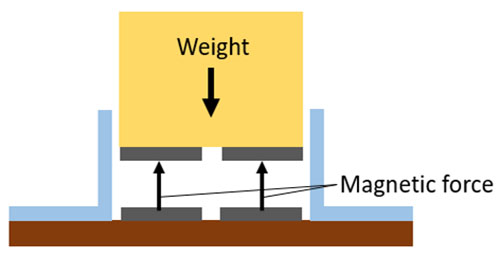
Two types of magnetic levitation systems exist: Electromagnetic suspension (EMS) and electrodynamics suspension (EDS). EMS employs magnets on the train's bottom and the guideway to lift the train, with additional magnets on the sides to prevent lateral displacement. This method is simpler and functions at zero speed.
In this application note, we analyze a proposed electromagnetic levitation system model for a semi-high-speed maglev train using EMWorks2D. The model includes levitation and guidance electromagnets, with the former lifting the vehicle and the latter centering it above the rail. Ferromagnetic components are steel 1010, and windings are copper.
![The studied electromagnetic levitation system [1]](/ckfinder/userfiles/images/figure-2-the-studied-electromagnetic-levitation-system-%5B1%5D.jpg)
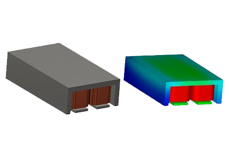
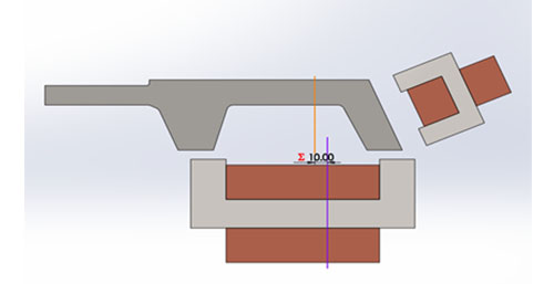
Figures 3a) and 3b) show respectively 3D and 2D CAD models built inside SOLIDWORKS. The 2D model is extracted from the 3D original geometry automatically using the 2D Simplification feature of EMWorks2D.
![CAD models of the presented magnetic levitation system, a) 3D model, b) 2D model [1]](/ckfinder/userfiles/images/figure-3-cad-models-of-the-presented-magnetic-levitation-system%2C-a%29-3d-model%2C-b%29-2d-model-%5B1%5D.jpg)
Simulation Results
Static magnetic simulations are performed using the Magnetostatic module of EMWorks2D. Parametric sweep feature is used to compute the magnetic field, levitation force, and guidance forces versus different parameters such as airgap length, applied current, etc. The levitation winding has 250 turns, while the guidance winding has 180 turns. The applied current is 15A and 7A respectively. Studying both levitation and guidance forces is particularly important to build an efficient and stable maglev system.
The figures below show the magnetic flux density plots several vertical airgap values. Clearly, the smaller is the airgap, the higher is the magnetic flux density. The flux results can be animated versus the parametric variable using EMWorks2D. Figure 6 contains an animation of the magnetic flux versus the Y position of the levitation magnet.
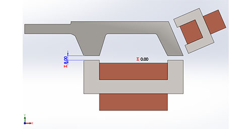
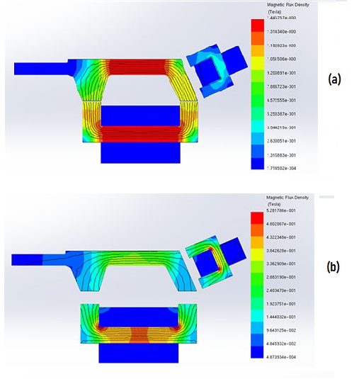
Figure 7 shows the force results versus the airgap size. The force decreases exponentially with the airgap. It has a peak value of 15 kN at 2 mm, while it is lower than 2 kN with an air gap smaller than 7 mm.
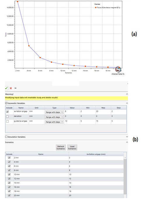
Figure 7 - Force Results Versus Airgap Computed Using a Parametric Study of EMWorks2D, a) Force Curve, B) Design Scenarios Page of EMWorks2D.
Figure 8 contains a comparison between force results versus current at different airgap lengths; the higher is the current and the smaller is the airgap, the larger is the force.
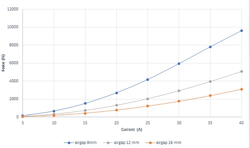
Figure 9 the lateral position of the rail is varied; both the levitation and guidance forces are measured. The lateral position of the rail impacts the stability of a maglev system. The rail should be maintained in an aligned position to maximize the levitation force and reduce the losses.
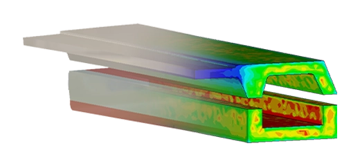
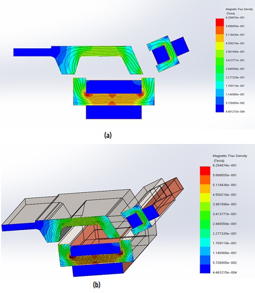
Figures 10a) and 10b) show the magnetic flux results at a maximum lateral deviation for an airgap of 10 mm. Figure 10b contains a superimposed plot of the 2D field plot with a cross-section view of the 3D model.
An animation of the magnetic field versus x position is shown in Figure 11; the airgap flux density decreases versus lateral displacement.
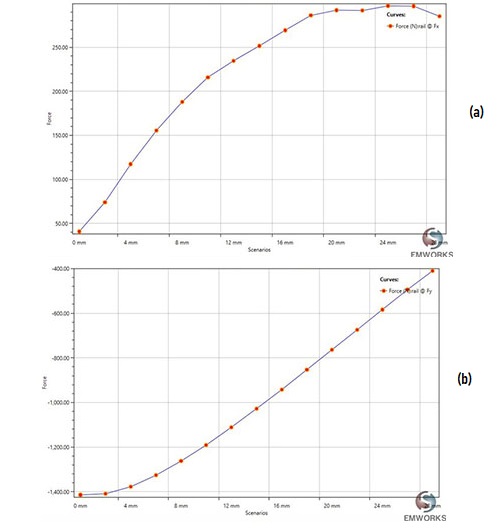
Figures 12a) and 12b) show, respectively, the guidance and levitation forces versus deviation. The lateral force, which should be maintained at low values, increases with the lateral deviation. Unlike the lateral force, the levitation force decreases with the x position.
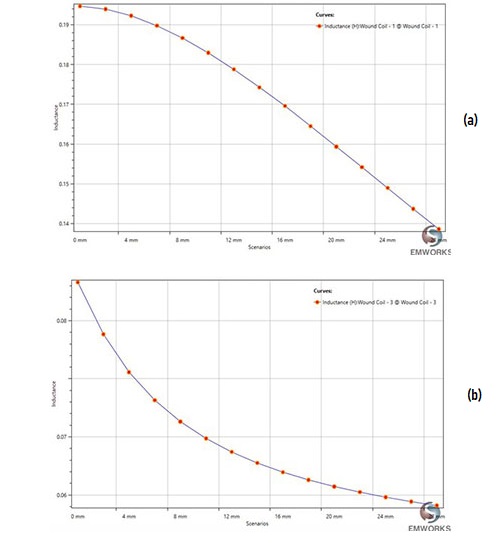
The inductances, for both levitation and guidance coils, are shown in the Figure 13; the larger is the deviation in the x position, the smaller are the inductances.
Optimizing the Levitation Force
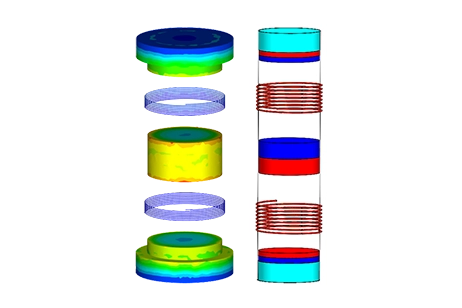
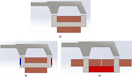
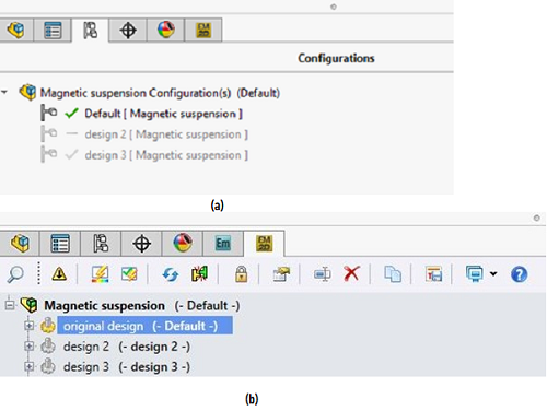
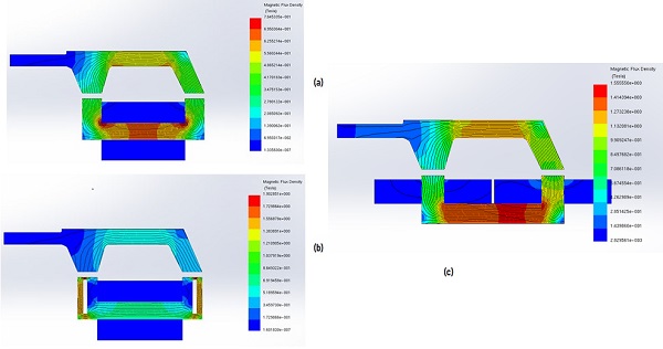
The levitation force is calculated for three distinct configurations, as depicted below. The original setup is illustrated in Figure 14a. In Figure 14b, a second configuration includes two additional magnets positioned laterally. Figure 14c showcases a third configuration featuring an added magnet at the bottom of the ferromagnetic core with two coils instead of one. Figures 15a) and 15b) display the multi-configuration page and EMWorks studies tree, respectively.
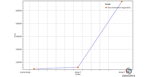
The magnetic field results for various configurations are visualized in Figure 16, while the force outcomes are depicted in Figure 17. Notably, the third configuration, featuring two adjacent coils, yields the highest force among the three configurations. This configuration can be regarded as an optimized system, showcasing superior performance compared to the others.
Conclusion
The application note provides a comprehensive examination of a magnetic levitation system designed for semi-high-speed maglev trains, utilizing EMWorks2D for simulation analysis. The study delves into various configurations of the levitation system, including the original setup and two additional designs incorporating extra magnets for enhanced levitation force. Through meticulous analysis, it was discovered that the third configuration, which features an added magnet at the bottom of the ferromagnetic core accompanied by two coils, yielded the highest levitation force among the examined setups. This optimized system demonstrated superior performance, offering a significant improvement over the original design. The findings from the simulations not only illustrate the effectiveness of 2D simulation in assessing and refining magnetic levitation systems but also highlight its crucial role in advancing the efficiency and reliability of transportation applications.
Reference
[1]: Min Kim, Jae-Hoon Jeong, Jaewon Lim†, Chang-Hyun Kim and Mooncheol Won. Design and Control of Levitation and Guidance Systems for a Semi-High-Speed Maglev Train. J Electr Eng Technol.2017; 12(1): 117-125