A Magnetic Levitation for Energy Harvesting
Transitioning to local renewable energy sources enhances energy security, reduces greenhouse gas emissions, and combats climate change impacts. Magnetic levitation energy harvesters efficiently convert mechanical vibrations into electricity, promoting sustainability by utilizing ambient energy sources. This study showcases EMWorks' capabilities in modeling and optimizing maglev-based energy harvesters.
Different Topologies of Maglev-Based Energy Harvesting Systems
The Electromagnetic Vibrational Energy Harvesters system comprises fixed magnets, a floating magnet, and coaxial coils. Positioned strategically, the fixed magnets create a stable levitation zone for the floating magnet. Coaxial coils surrounding the levitating magnet capture magnetic field variations. Polarity arrangement and a hollow plastic tube constrain lateral motion, enabling efficient energy harvesting.
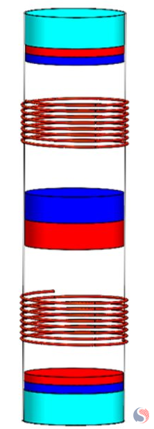
Fig. 1. A Typically Magnetic Levitation-Based Energy Harvesting System
Here are some of the main topologies used in magnetic levitation energy harvesters:
-
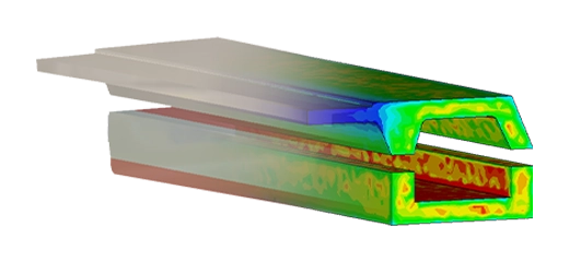
Single-Coil Topology (Figure 2): In this configuration, a single coil is used to capture the magnetic field variation induced by the relative motion between the magnet and the coil.
-
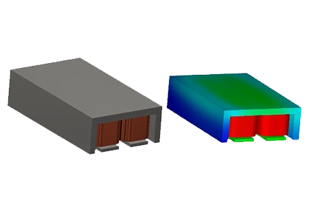
Bistable Topology (Figure 3): Bistable energy harvesters utilize two coils and one floating magnet. The magnets are positioned such that they can attract or repel each other depending on their relative positions.
-
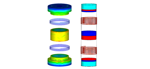
Multi-Coil multi-magnets Topology (Figures 4 and 5): This topology employs two coils and multiple magnets arranged in specific configurations.
![Single Coil: Single Floating Magnet [1]](/ckfinder/userfiles/images/single-coil_single-floating-magnet-%5B1%5D-26-07-2023.png)
Fig. 2. Single Coil: Single Floating Magnet [1]
![Two Coils: Single Floating Magnet [2]](/ckfinder/userfiles/images/two-coils_single-floating-magnet-%5B2%5D-26-07-2023.png)
Fig. 3. Two Coils: Single Floating Magnet [2]
![Two Coils: Multi Floating Magnets [3]: Uniform Magnetization](/ckfinder/userfiles/images/-two-coils_multi-floating-magnets-%5B3%5D-uniform-magnetization--26-07-2023.png)
Fig. 4. Two Coils: Multi Floating Magnets [3]: Uniform Magnetization
![Two Coils: Multi Floating Magnets [3]: Halbach Magnetization](/ckfinder/userfiles/images/-two-coils_multi-floating-magnets-%5B3%5D-halbach-magnetization-26-07-2023.png)
Fig. 5. Two Coils: Multi Floating Magnets [3]: Halbach Magnetization
Design Parameters
Table 1 summarizes the design parameters of the different topologies, to be simulated using EMWorks. All magnets are made of NdFeb N4212 material and the coils are made of copper material. The system is prevented by enclosing it in a hollow plastic tube.
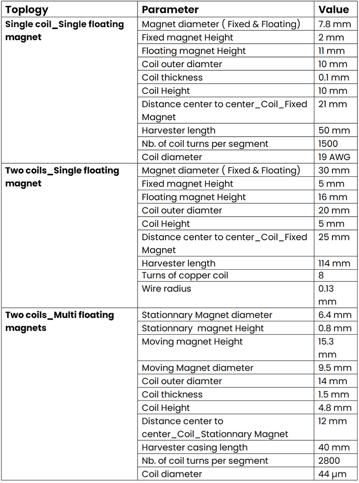
Table 1. Design Parameters of the Simulated Topologies
EMWorks Solutions
By considering the magnet properties, geometry, and coil arrangement, EMS analyzes factors such as magnetic flux density, field gradients, and interactions between magnets and coils. This analysis aids in optimizing the magnet configuration and coil design for efficient energy conversion.
Several important outputs can be investigated to assess the performance and effectiveness of the system.
Here are some key outputs to consider:
Restoring Force
The restoring force refers to the force that brings the magnetically levitated object back to its equilibrium position after it has been displaced.
The restoration force is often actively controlled and adjusted to regulate the position of the levitating component. Simulation using EMWorks can help in designing and optimizing the control mechanisms that generate the restoration force. By analyzing the forces acting on the levitating component, engineers can develop feedback control systems that adjust the magnetic fields or currents to maintain the desired levitation height and stability.
The restoring force plot is typically represented as a graph with the applied displacement on the x-axis and the restoring force on the y-axis.
Figures 6, 7, 8, and 9 show the plot of the restoring force for the four simulated topologies, respectively. The plots show how the restoring force changes as the levitating component is displaced from its equilibrium position. Initially, at small displacements, the restoring force may increase or decrease linearly or follow a nonlinear relationship. The specific behavior depends on the design and characteristics of the Maglev-based energy harvester topology being simulated.
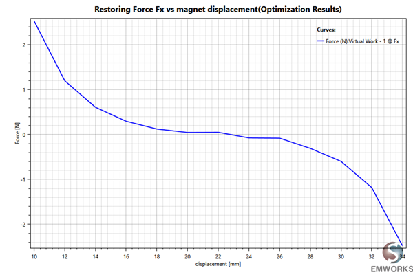
Fig. 6. Restoring Force - Topology 1
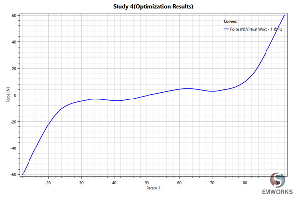
Fig. 7. Restoring Force - Topology 2
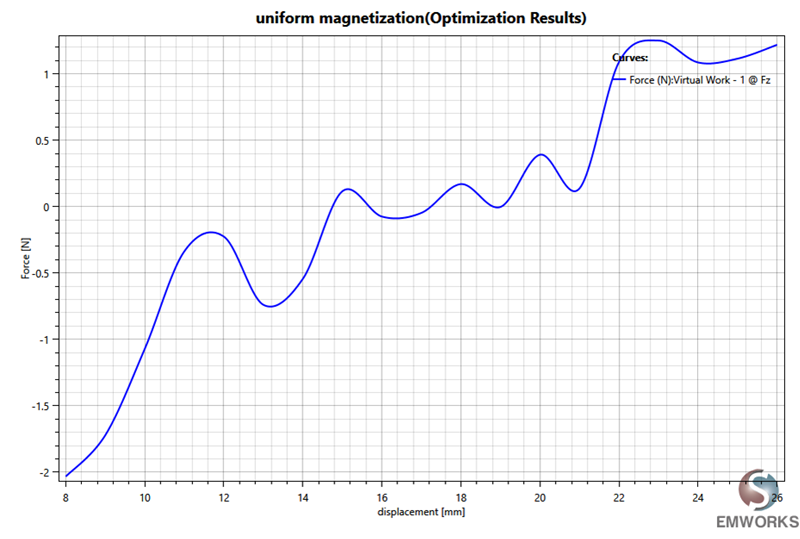
Fig. 8. Restoring Force - Topology 3: Uniform Magnetization
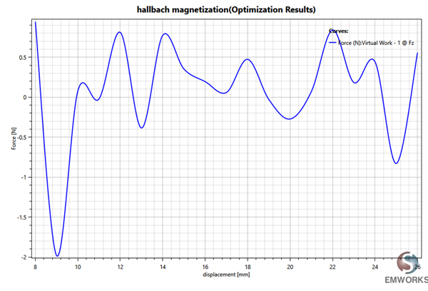
Fig. 9. Restoring Force - Topology 3: Halbach Magnetization
The Induced Voltage
The induced voltage in each coil follows Faraday's law of electromagnetic induction. The changing magnetic field through the coils due to the motion of the magnet generates an electromotive force (EMF), resulting in an induced voltage across the coils. The induced voltage is directly proportional to the power generated by the energy harvester system. It represents the electrical energy generated through the conversion of mechanical energy.
In a Maglev-based energy harvester system with a single floating magnet, the induced voltage in the coil exhibits an oscillatory behavior. As the magnet oscillates or vibrates in its levitated state, the magnetic field through the coil changes periodically, resulting in alternating induced voltages with a frequency corresponding to the magnet's motion (Figure 10). In the "Two coils-single floating magnet" topology, the induced voltage in each coil can have a phase difference. Depending on the relative positions of the coils and the magnet, the induced voltage in one coil may be ahead or behind the other coil in terms of its waveform. The phase relationship can be controlled by adjusting the coil positions and orientations (Figure 11).
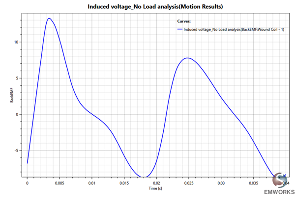
Fig. 10. Induced Voltage in a Single Coil
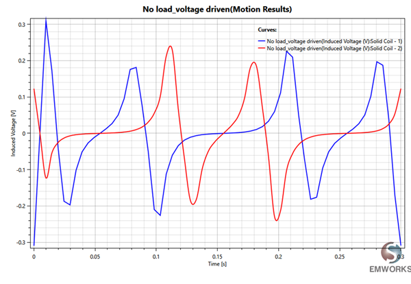
Fig. 11. Induced Voltage in Two Coils
Magnetic Field
The magnetic field output from a Maglev-based energy harvester system is of great importance for several reasons:
-
The magnetic field is responsible for inducing electrical currents in the harvester's coils, which generate electricity. Therefore, the strength and stability of the magnetic field directly impact the power generation capability of the system.
-
The stability and reliability of the energy harvester system depend on the consistency and durability of the magnetic field. Variations or fluctuations in the magnetic field strength can lead to inconsistent power output or even system failures. Therefore, a thorough simulation using the electromagnetic FEA tool, EMWorks allows for the evaluation of the magnetic field's stability under various operating conditions, ensuring the system's reliability.
-
Magnetic Interference: The magnetic field generated by the Maglev-based energy harvester system may interact with other nearby magnetic fields or sensitive equipment. Understanding the magnetic field's behavior and its potential interference with surrounding devices is crucial for ensuring compatibility and preventing any adverse effects on neighboring systems.
Figures 12, 13, 14, and 15 show the distribution of the magnetic flux density when the floating magnet is in the equilibrium position for the four simulated topologies, respectively.
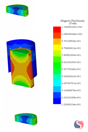
Fig. 12. Magnetic Flux Density Distribution - Topology 1
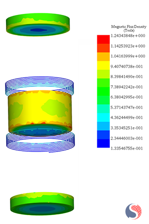
Fig. 13. Magnetic Flux Density Distribution - Topology 2
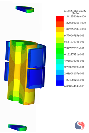
Fig. 14. Magnetic Flux Density Distribution - Topology 3: Uniform Magnetization
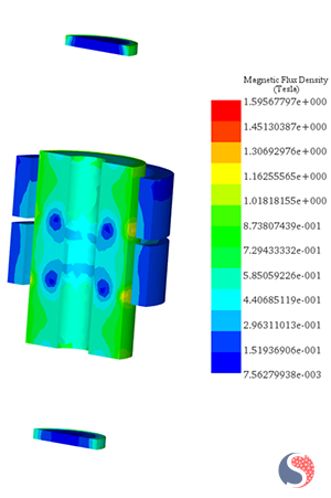
Fig. 15. Magnetic Flux Density Distribution - Topology 3: Halbach Magnetization
Conclusion
Generating sustainable and clean energy is crucial for combating climate change, preserving the environment, safeguarding human health, ensuring energy security, driving economic growth, fostering innovation, and promoting global collaboration. It is a vital step towards creating a sustainable and thriving future for us and future generations. Leveraging EMS simulations enhances the efficiency, performance, and reliability of maglev-based energy harvesters, driving advancements in sustainable energy generation. They provide a comprehensive understanding of magnetic fields, predict induced voltage and power, analyze stability, and identify potential interference. These capabilities contribute to the development of efficient and high-performing energy harvesting systems.
References
[1] Marco P. Soares dos Santos, Jorge A. F. Ferreira, José A. O. Simões, Ricardo Pascoal, João Torrão, Xiaozheng Xue& Edward P. Furlani, Magnetic levitation-based?
electromagnetic energy harvesting: a semi-analytical non-linear model for energy transduction?
[2] Tobias Willemoes Jensen, Andrea R. Insinga, Johan Christian Ehlers & Rasmus Bjørk, The full phase space dynamics of a magnetically levitated electromagnetic vibration harvester?
[3] https://www.degruyter.com/document/doi/10.1515/ehs-2013-0005/html