A Wilkinson Power Divider
The Wilkinson power divider, introduced by Ernest Wilkinson in 1960, can split an input signal into two in-phase outputs or combine two equal-phase inputs. It uses a quarter-wave transformer to match the split ports to the common port and includes a resistor between the second and third ports for simultaneous matching. In this example, we model a Printed Wilkinson RF Power Splitter at 9 GHz using HFWorks, presenting reflection, transmission coefficients, and other parameters.
.jpg)
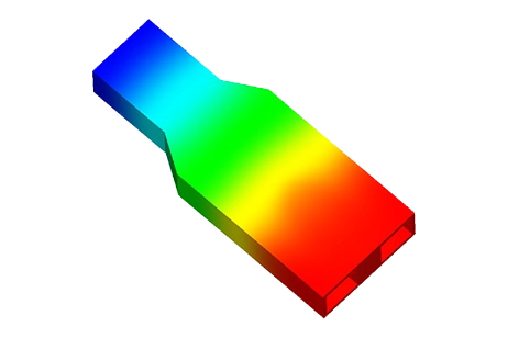
Figure 1 - 3D view of the modeled Wilkinson divider
The model has been optimized using the best dimensions, which are described in this figure.
.jpg)
Simulation
The simulation of this power divider was conducted using a Scattering Parameters study from 4 GHz to 12 GHz, and it efficiently split the power into two in-phase outputs.
Solids and Materials
Considering the skin effect's shallow penetration, we can model multiple conductors by assigning air to them. The substrate material can be selected from the library or defined by the user. Additionally, we can specify Signal and PEC boundary conditions for the RF carrier and the ground metal beneath the substrate, respectively.
Load/ Restraint
The ports are connected to the main excitation path's pad, with the RF conductor assigned a signal boundary condition..
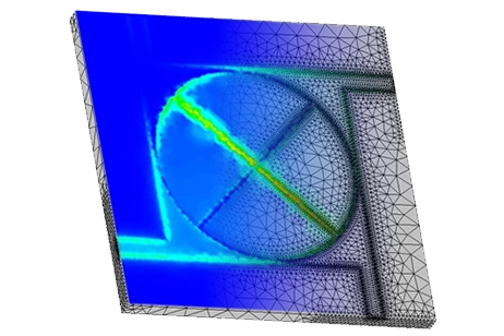
Meshing
The model doesn't have complex shapes, so a uniform mesh for the assembly should suffice without the need for specific mesh controls.
Results
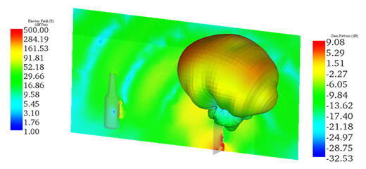
Animating the 3D electric field distribution by varying the omega-T angle provides insights into how the wave propagates into the port and splits within the two branches of the divider. Initially, we can examine the reflection coefficient curve at the port to determine the frequency that offers the best matching and optimal propagation into the two ports. However, it's also possible to visualize the near field even for frequencies where no propagation occurs.
Figure 3 - Wave propagation in the power divider at 10 GHz
This figure shows plots of the variation of the reflection coefficient and insertion loss of the divider.
.jpg)
Blue= S11; Red=S21; Green=S31
Figure 4 - Variations of reflection coefficient and insertion losses at the outputs
The two output ports exhibit a 3 dB power loss relative to the input, indicating a well-balanced power split. In the figure, we display the generalized Scattering Parameters matrix in dB/Phase format, represented in polar form with magnitude expressed in dB. It's evident that S21 and S31 are nearly identical at -3 dB (0.5), and both isolation and return loss are better than -14 dB.
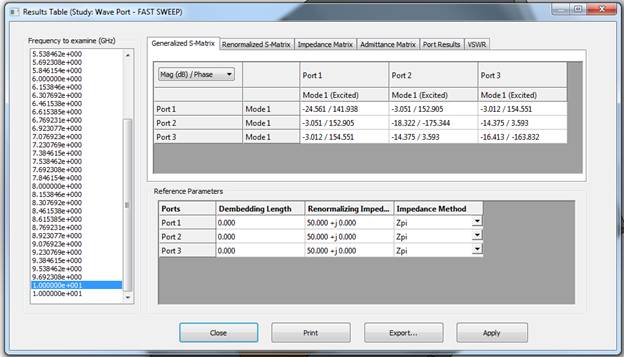
Figure 5 - Results table with various calculated parameters (within the tabs)
Conclusion
In conclusion, the application note successfully demonstrates the modeling and simulation of a Printed Wilkinson RF Power Splitter operating at 9 GHz using HFWorks. By optimizing the dimensions and conducting a Scattering Parameters study from 4 GHz to 12 GHz, the power divider efficiently splits the input signal into two in-phase outputs. The simulation reveals insights into the wave propagation within the divider, reflected in the reflection coefficient curve and near-field visualization. The results indicate a well-balanced power split with a 3 dB power loss relative to the input, supported by the nearly identical S21 and S31 parameters at -3 dB. With better isolation and return loss exceeding -14 dB, the power divider proves effective in its intended application. Overall, the study showcases the capabilities of HFWorks in analyzing and optimizing RF power divider designs for various frequency ranges.