A Coplanar Waveguide
The Coplanar Waveguide (CPW), invented by Cheng P. Wen in 1969, features a central conductor flanked by two ground planes on the same dielectric side, optimizing electromagnetic field containment. Its variant, the Grounded Coplanar Waveguide (GCPW), introduces an additional ground plane on the dielectric's opposite side for enhanced performance with thick substrates, addressing the microstrip's impedance and radiation loss issues at high frequencies. This study utilizes HFWorks to examine a GCPW's efficacy on a 0.030" isotropic substrate.
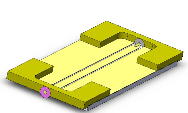
Figure 1 - the structure's 3D view
The mesh accuracy for the structure, particularly around vias and ports, is critical. HFWorks automatically generates a suitable mesh based on the structure's dimensions, but users have full control to adjust the mesh size and apply specific mesh controls to areas they deem more critical, ensuring detailed and precise simulations.
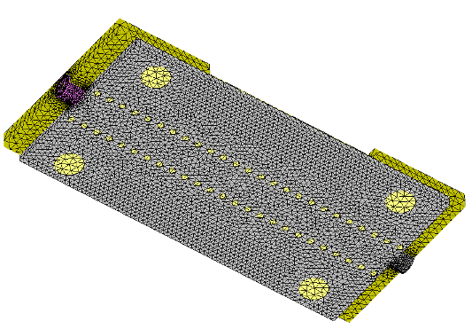
Figure 2 - Mesh of the structure
Simulation
To simulate this transition's behavior, including insertion and return loss within the desired frequency band and matching at input and output, a Scattering Parameters study is created, spanning 20 frequencies from 0.2 GHz to 20 GHz, centering at 10 GHz. The simulation involves assigning radiation boundaries to limit reflection and accurately measure radiation, enhancing the simulation's precision. Users can adjust results and explore electrical parameters like insertion and return losses, offering flexibility in analyzing the transition's performance across a wide frequency range.
Load/ Restraint
In the coplanar waveguide design, signal and ground conductors are key components. During the material assignment phase, these conductors can be designated as Signal and Perfect Electric Conductor (PEC) materials, respectively. This step is crucial for accurately simulating the waveguide's electromagnetic behavior.
Results
For analyzing transitions between different transmission supports, utilizing 3D and 2D plots to examine insertion and return losses is highly effective. These visualizations provide a clear representation of the filter's performance, allowing for a detailed understanding of its efficiency and signal integrity across the transition.
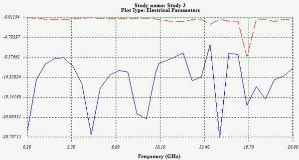
Figure 3 - Insertion (Red) and return (Blue) losses
The insertion loss within the frequency band is notably low, indicating efficient signal transmission across most of the band. The return loss, while fluctuating, maintains good matching performance, highlighting effective impedance matching. For a detailed analysis of matching issues, utilizing a Smith chart plot for the return loss provides deeper insights, offering a more nuanced understanding of the system's impedance behavior.
.jpg)
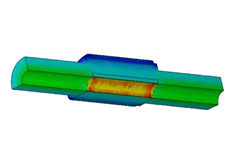
Figure 4 - Electric field vector distribution on the circuit at the aimed frequency (8.3 GHz)
The figure illustrates the electric field distribution at 8.4 GHz, capturing the moment electromagnetic waves traverse the circuit and reach the second SMA port. When animated, this visualization provides a clear view of wave propagation, enhancing understanding of the circuit's electromagnetic behavior at this specific frequency.
Conclusion
This application note delves into the analysis of a Grounded Coplanar Waveguide (GCPW) designed for high-frequency applications, building on the original Coplanar Waveguide (CPW) concept by Cheng P. Wen in 1969. Utilizing HFWorks, the study examines the GCPW's performance on a 0.030" isotropic substrate, highlighting its advantages in electromagnetic field containment and addressing the limitations of microstrips such as impedance and radiation loss issues at high frequencies. Through a comprehensive Scattering Parameters study spanning from 0.2 GHz to 20 GHz, with a focus on 10 GHz, the simulation assesses insertion and return loss, providing insights into the waveguide's efficiency across a broad frequency range. The results showcase low insertion loss, indicating efficient signal transmission, and fluctuating yet effective return loss, demonstrating good impedance matching. Detailed visualizations, including electric field distribution at the aimed frequency of 8.4 GHz, offer a deeper understanding of the waveguide's operational dynamics, proving the GCPW's efficacy in enhancing signal integrity and performance in high-frequency applications.
References
Southwest Microwave, Inc. Optimizing Test Boards for 50 GHz End Launch Connectors: Grounded Coplanar Launches and Through Lines on 30 mil Rogers 4350 with Comparison to Microstrip